7SR11 & 7SR12 Commissioning and Maintenance Guide
©2017 Siemens Protection Devices Limited Chapter 6 Page 37 of 72
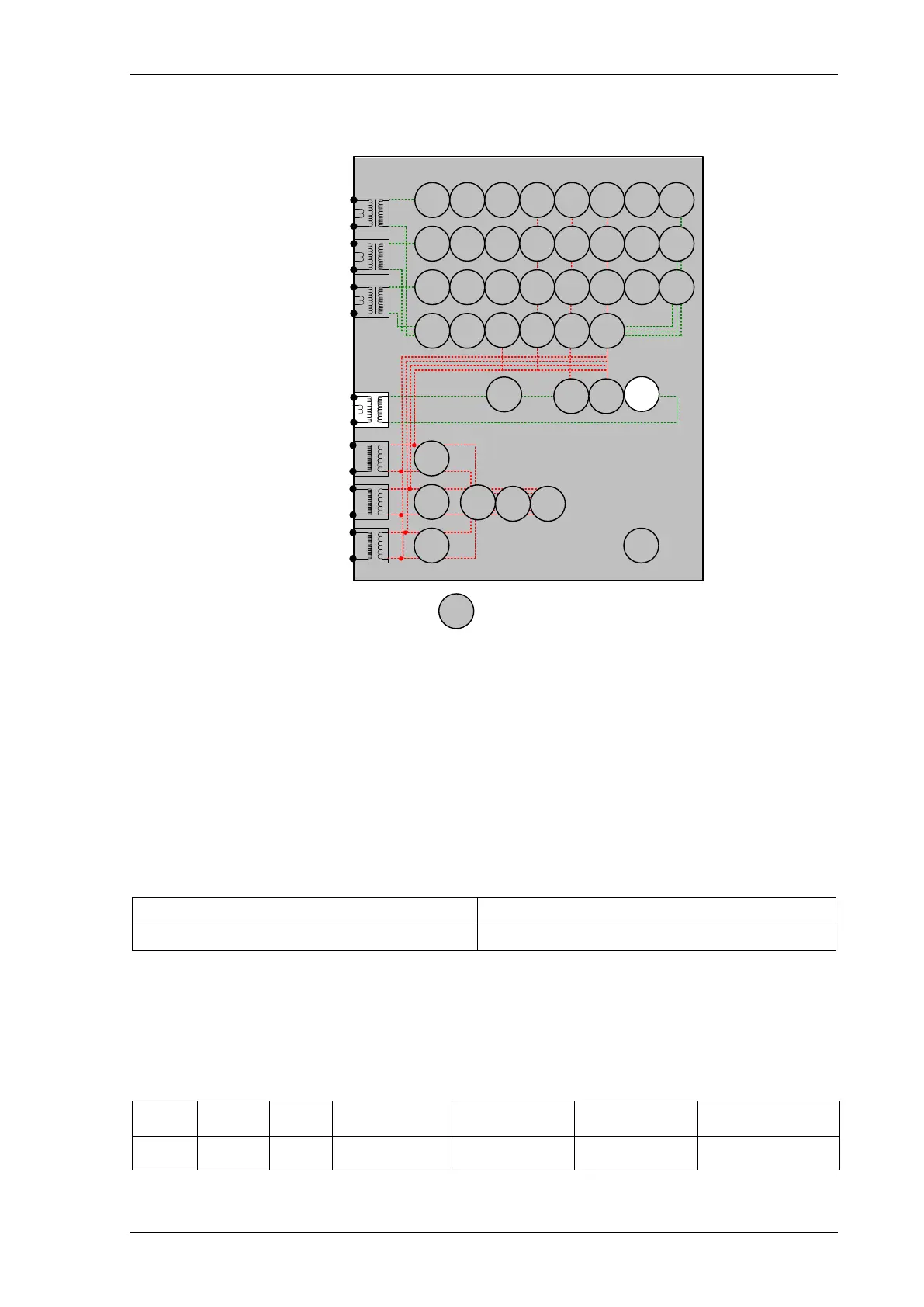
2.10 Restricted Earth fault (64H)
7SR12
46
BC
46
NPS
(x2)
37
(x2)
49
50
BF
51V
V
L1
(V
A
)
V
L2
(V
B
)
V
L3
(V
C
)
I
L1
(I
A
)
81
HBL
2
37
(x2)
49
50
BF
51V
I
L2
(I
B
)
81
HBL
2
37
(x2)
49
50
BF
51V
I
L3
(I
C
)
81
HBL
2
I
4
(I
G
)
74
T/
CCS
NOTE: The use of some
functions are mutually exclusive
67/
50
(x4)
67/
51
(x4)
67/
50N
(x4)
67/
50
(x4)
67/
50
(x4)
67/
51
(x4)
67/
51
(x4)
67/
51N
(x4)
67/
50
SEF
67/
51
SEF
27
59
(x4)
27
59
(x4)
27
59
(x4)
79
Optional
Note:
Example shows
Voltage Config =
Van, Vbn, Vcn
60
CTS
60
VTS
64H
50BF
51c
51c
51c
47
(x2)
59N
(x2)
81
(x4)
Figure 2-11 Restricted Earth Fault
Voltage Inputs: n/a
Current Inputs: I
4
(I
REF
)
Disable: 51SEF, 50SEF, 79
Map Pickup LED: 64H - Self Reset
The setting resistance should be measured and the value compared to that specified in the settings data. Both
values should be recorded.
Settings Data Resistor Value
The high value of setting resistance R will often interfere with secondary current injection when using a digital test
set. It is normal practice in these cases to short out the series resistor to allow testing, the shorting link should be
removed after testing.
Since the DTL setting is generally small the pick-up setting can be tested by gradually increasing current until
element operates. The relay should be disconnected from the current transformers for this test.
Apply 2x setting current if possible and record operating time
(Amps)
(sec)
Amps
2 x Is

 Loading...


