7SR11 & 7SR12 Commissioning and Maintenance Guide
©2017 Siemens Protection Devices Limited Chapter 6 Page 54 of 72
2.16 Power (32)
7SR12
46
BC
46
NPS
(x2)
37
(x2)
49
50
BF
51V
V
L1
(V
A
)
V
L2
(V
B
)
V
L3
(V
C
)
I
L1
(I
A
)
81
HBL
2
37
(x2)
49
50
BF
51V
I
L2
(I
B
)
81
HBL
2
37
(x2)
49
50
BF
51V
I
L3
(I
C
)
81
HBL
2
I
4
(I
G
)
74
T/
CCS
NOTE: The use of some
functions are mutually exclusive
67/
50
(x4)
67/
51
(x4)
67/
50N
(x4)
67/
50
(x4)
67/
50
(x4)
67/
51
(x4)
67/
51
(x4)
67/
51N
(x4)
67/
50 G/
SEF
67/
51 G/
SEF
27
59
(x4)
27
59
(x4)
27
59
(x4)
47
(x2)
79
Optional
59N
(x2)
Note:
Example shows
Voltage Config =
Van, Vbn, Vcn
60
CTS
60
VTS
50BF
51c
51c
51c
64H
81
(x4)
32
(x2)
32
(x2)
32
(x2)
50
AFD
(x2)
50
AFD
(x2)
50
AFD
(x2)
32S
55
(x2)
55
(x2)
55
(x2)
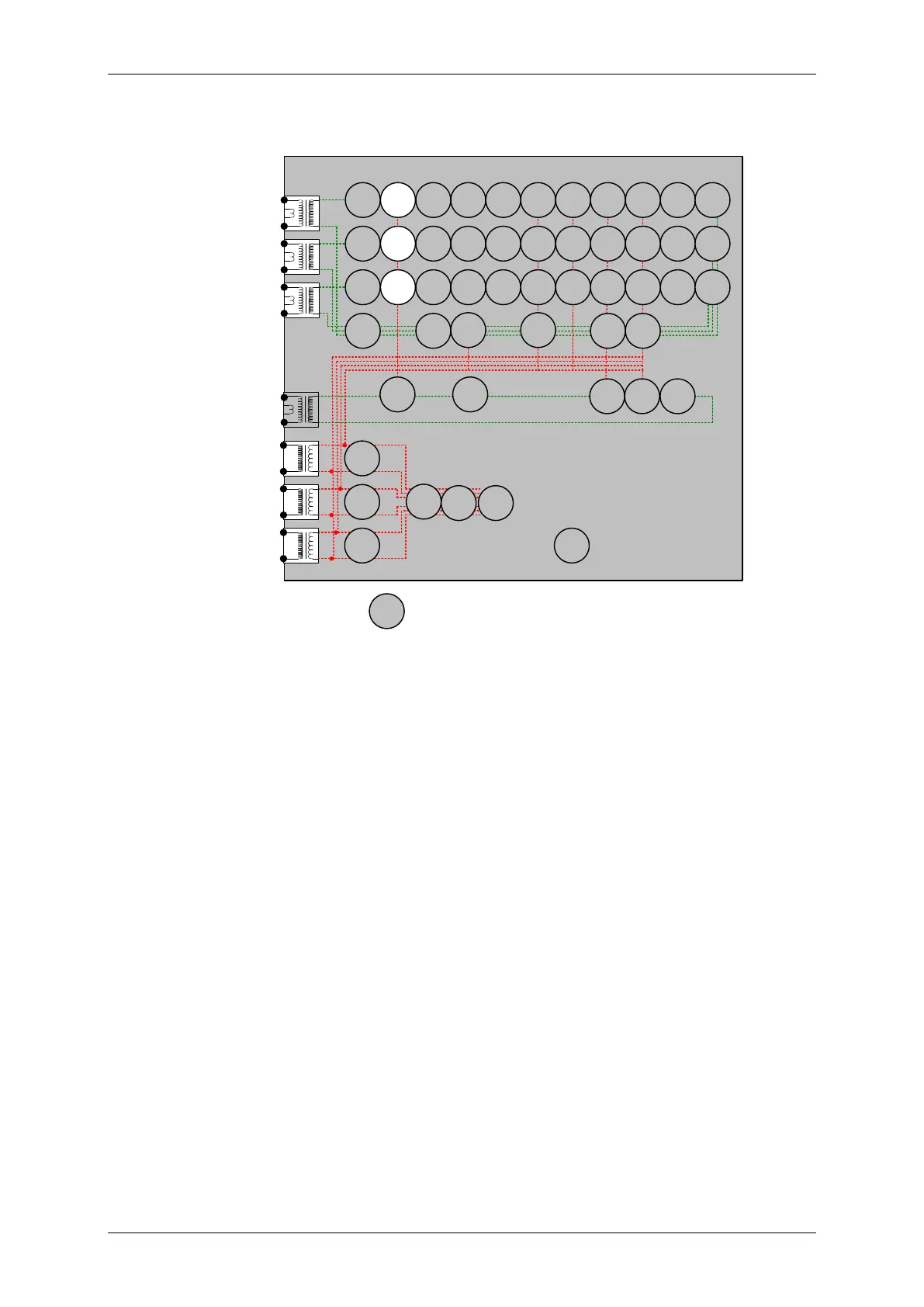
Figure 2-19 Power
Voltage Inputs: V
L1
(V
A
), V
L2
(V
B
), V
L3
(V
C
)
Current Inputs: I
L1
(I
A
), I
L2
(I
B
), I
L3
(I
C
),
Disable: 50, 51,27
Map Pickup LED: 32-n - Self Reset
This function can be tested by application 3P current and voltage. For Over-power, the elements with the highest
setting should be tested first and for Under-power the elements with the lowest settings should be tested first. The
elements with other settings can then be tested without need to disable the elements already tested.
From the nominal power setting Sn gradually increase/decrease applied voltage or current until 32-n operation
occurs.
If the 32-n Delay setting is long it will be advantageous to map the function to temporarily drive the relevant
Pickup output in the Pickup Config sub-menu in the Output Config menu as this will allow the Pick-up led to
operate for the function. If the delay setting is short the operation of the element can be easily checked directly.
The current or voltage should then be decreased/increased until the element resets.
If the element is set as 32-n U/C Guarded, The applied current must be above the 32 U/C Guard Setting.
Apply setting power +10% for Over-power or -10% for Under-power and record operating time.

 Loading...


