7SR11 & 7SR12 Description Of Operation
Chapter 1 Page 34 of 88 ©2017 Siemens Protection Devices Limited
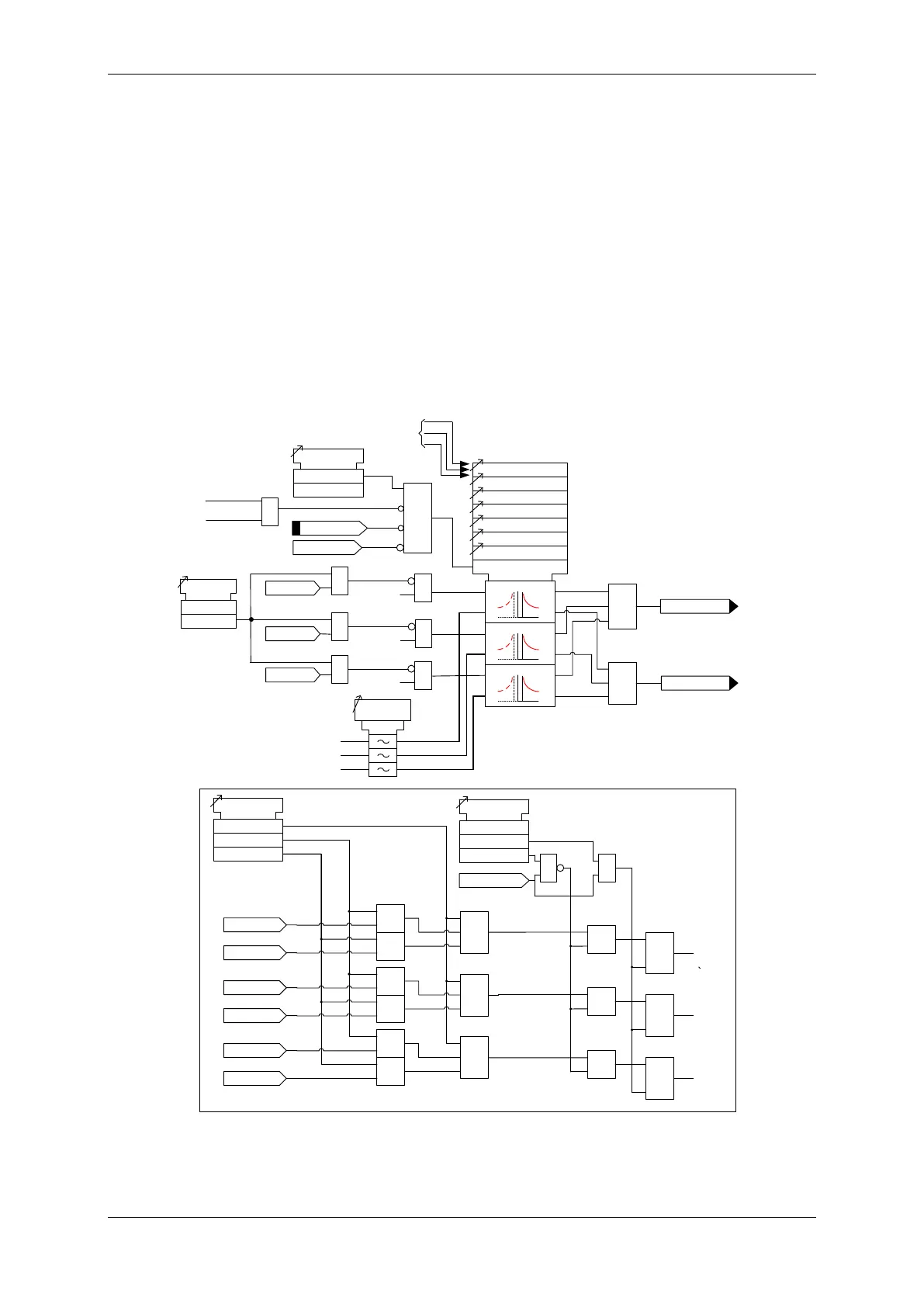
A fixed additional operate time can be added to the characteristic using 51-n Follower DTL setting.
Where directional elements are present the direction of operation can be set using 51-n Dir. Control setting.
Directional logic is provided independently for each 51-n element
Operation of the time delayed overcurrent elements can be inhibited from e.g. giving the option of using two
elements set to forward and two to reverse.
Inhibit 51-n A binary or virtual input.
79 P/F Inst Trips: 51-n When ‘delayed’ trips only are allowed in the auto-reclose sequence
(79 P/F Prot’n Trip n = Delayed).
51c Activation of the cold load settings.
50-n Inrush Action: Block Operation of the inrush current detector function.
51-n VTSAction: Inhibit Operation of the VT Supervision function (7SR1205 & 7SR1206).
≥1
≥1
General Pickup
51-n
51-n Setting
51-n Charact
51-n Time Mult
51-n Delay (DTL)
51-n Reset
c
Forward
Reverse
51-n Dir Control
Non-Dir
≥1
&
&
≥1
&
&
≥1
&
&
51-n Follower DTL
L1 Dir En
L2 Dir En
L3 Dir En
L1 Dir En
L2 Dir En
L3 Dir En
IL1 Fwd
IL1 Rev
IL2 Fwd
IL2 Rev
IL3 Fwd
IL3 Rev
&
&
&
≥1
≥1
≥1
Non Dir
51-n VTS Action
Off
Inhibit
VT Fail
&
51-n Min. Operate Time
&
IL1
IL2
IL3
50/51
Measurement
&
See Voltage Controlled
Overcurrent (51V)
L1 81HBL2
51c
51-n Inrush
Action
Off
Inhibit
&
L3
L2
L1
L2 81HBL2
L3 81HBL2
&
&
&
&
&
c
Pickup
trip
c
Pickup
trip
c
Pickup
trip
Inhibit 51-n
51-n Element
Enabled
Disabled
&
79 P/F Inst Trips
= 51-n
79 P/F Prot’n Trip n
= Delayed
AUTORECLOSE
Figure 3-3 Logic Diagram: Time Delayed Overcurrent Element

 Loading...


