7SR11 & 7SR12 Description Of Operation
Chapter 1 Page 38 of 88 ©2017 Siemens Protection Devices Limited
The 51-n Reset setting can apply a definite time delayed reset, or when the operation is configured as an IEC or
ANSI or user characteristic if the reset is selected as IEC/ANSI (DECAYING) reset the associated reset curve will
be used. The reset mode is significant where the characteristic has reset before issuing a trip output – see
‘Applications Guide’
A minimum operate time for the characteristic can be set using the 51N-n Min. Operate Time setting.
A fixed additional operate time can be added to the characteristic using the 51N-n Follower DTL setting.
Where directional elements are present the direction of operation can be set using 51N-n Dir. Control setting.
Directional logic is provided independently for each 51N-n element.
Operation of the time delayed earth fault elements can be inhibited from:
Inhibit 51N-n A binary or virtual input.
79 E/F Inst Trips: 51N-n When ‘delayed’ trips only are allowed in the auto-reclose sequence
(79 E/F Prot’n Trip n = Delayed).
50-n Inrush Action: Block Operation of the inrush current detector function.
51N-n VTSAction: Inhibit Operation of the VT Supervision function (7SR1205 & 7SR1206).
General Pickup
51N-
n
51N-n Setting
51N
-
n Charact
51N-n Time Mult
51N
-n Min Operate Time
51N-n Reset
If directional elements are not present this block is
omitted and the '
51N-
n Dir En' signal is set TRUE.
Forward
Reverse
51N-
n Dir.
Control
Non-Dir
≥1
&
&
51N-n Dir En
67N Fwd.
67N Rev
.
51N
-n VTS Action
Off
Non Dir
Inhibit
VT Fail
&
&
&
≥1
IL1
IL2
IL3
I
N
51
N-n Delay
(DTL)
51N-
n Follower DTL
c
Pickup
trip
Inhibit
50
N-n
&
51N-n Element
Enabled
Disabled
81
HBL2
51
N-
n Inrush
Action
Off
Inhibit
&
51N-n Dir En
&
79 P
/F Inst Trips
= 51N-n
79 P/F Prot’n Trip n
= Delayed
AUTORECLOSE
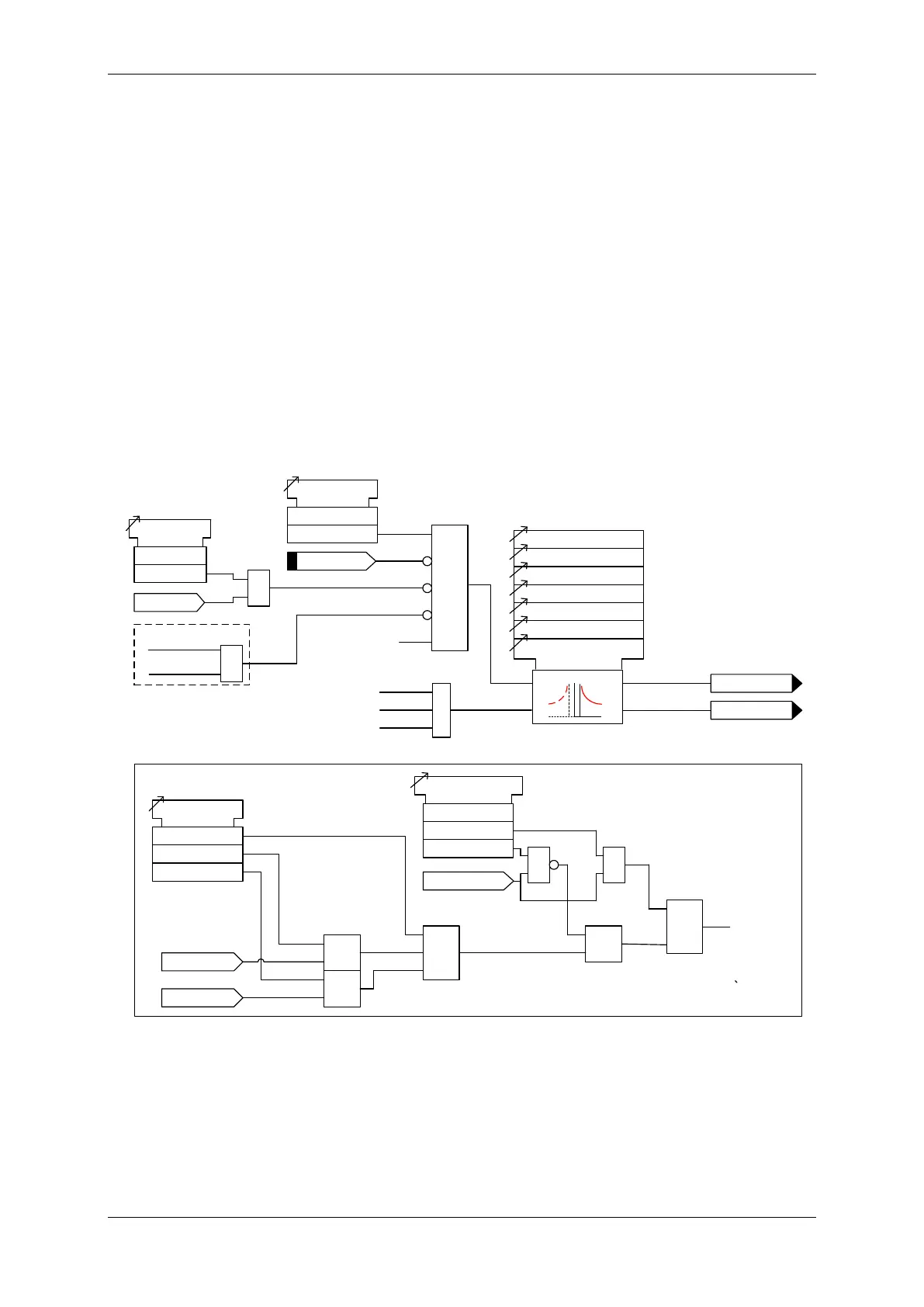
Figure 3-7 Logic Diagram: Derived Time Delayed Earth Fault Protection

 Loading...


