7SR11 & 7SR12 Description Of Operation
Chapter 1 Page 54 of 88 ©2017 Siemens Protection Devices Limited
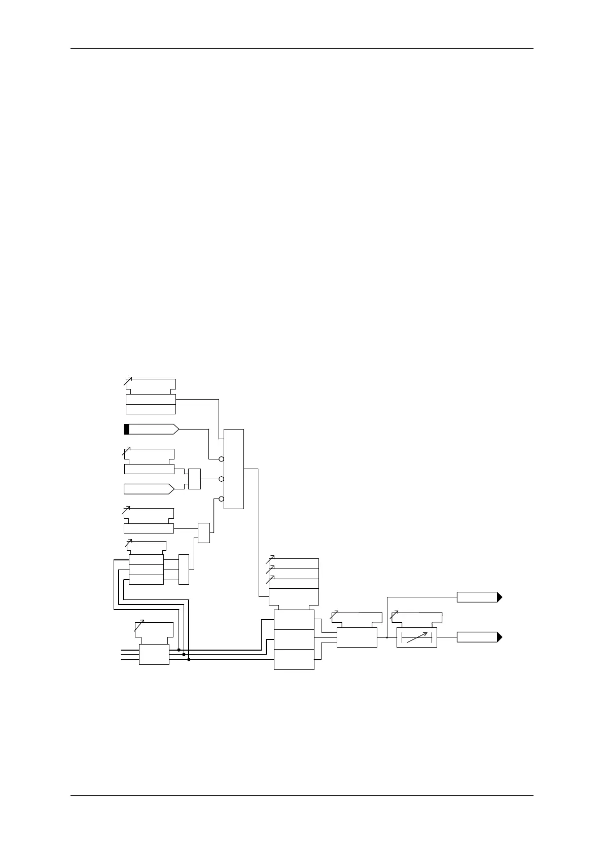
3.12 Voltage Protection: Phase Under/Over Voltage (27/59) –
7SR12
In total four under/over voltage elements are provided 27/59-1, 27/59-2, 27/59-3 & 27/59-4.
The relay utilises fundamental frequency RMS voltage for this function. All under/over voltage elements have a
common setting to measure phase to phase (Ph-Ph) or phase to neutral (Ph-N) voltage using the Voltage Input
Mode setting.
Voltage elements can be blocked if all phase voltages fall below the 27/59 U/V Guard setting.
27/59-n Setting sets the pick-up voltage level for the element.
The sense of the element (undervoltage or overvoltage) is set by the 27/59-n Operation setting.
The 27/59-n O/P Phases setting determines whether the time delay is initiated for operation of any phase or only
when all phases have detected the appropriate voltage condition. An output is given after elapse of the 27/59-n
Delay setting.
The 27/59-n Hysteresis setting allows the user to vary the pick-up/drop-off ratio for the element.
Operation of the under/over voltage elements can be inhibited from:
Inhibit 27/59-n A binary or virtual input.
27/59-n VTSInhibit: Yes Operation of the VT Supervision function (7SR1205 & 7SR1206).
27/59-n U/V Guarded Under voltage guard element.
``````````````````````````````````````````````````````````````````````````````
Any (≥1)
All (&)
or
> <
or
> <
or
> <
General Pickup
27/59-n
Inhibit 27/59-n
27/59-n Hysteresis
27/59-n Delay
27/59-n O/P Phases
c
&
27/59-n Setting
27/59-n Operation
27/59-n
Enabled
Disabled
27/59-n VTS Inhibit
Yes
VT Fail
&
27/59 U/V Guarded
Yes
&
Voltage
Input
Mode
VL1
VL2
VL3
<
&
27/59 U/V Guard
Setting
PH-PH
Or
PH-N
<
<
Figure 3-27 Logic Diagram: Under/Over Voltage Elements (27/59)

 Loading...


