7SR11 & 7SR12 Applications Guide
©2017 Siemens Protection Devices Limited Chapter 7 Page 45 of 48
5.4 Trip/Close Circuit Supervision (74T/CCS)
Binary Inputs may be used to monitor the integrity of the CB trip and close circuit wiring. A small current flows
through the B.I. and the circuit. This current operates the B.I. confirming the integrity of the auxiliary supply, CB
coil, auxiliary switch, C.B. secondary isolating contacts and associated wiring. If monitoring current flow ceases,
the B.I. drops off and if it is user programmed to operate one of the output relays, this can provide a remote alarm.
In addition, an LED on the relay can be programmed to operate. A user text label can be used to define the
operated LED e.g. “Trip CCT Fail”.
The relevant Binary Input is mapped to 74TCS-n or 74CCS in the INPUT CONFIG>INPUT MATRIX menu. To
avoid giving spurious alarm messages while the circuit breaker is operating the input is given a 0.4s Drop-off
Delay in the INPUT CONFIG>BINARY INPUT CONFIG menu.
To provide an alarm output a normally open binary output is mapped to 74TCS-n or 74CCS-n.
5.4.1 Trip Circuit Supervision Connections
The following circuits are derived from UK ENA S15 standard schemes H5, H6 and H7.
For compliance with this standard:
Where more than one device is used to trip the CB then connections should be looped between the
tripping contacts. To ensure that all wiring is monitored the binary input must be at the end of the looped
wiring.
Resistors must be continuously rated and where possible should be of wire-wound construction.
Scheme 1 (Basic)
R
BI
+
ve -ve
+
BO 1 BO n
Remote
Alarm
BO
R
TRIP COIL
52a
52b
-
Circuit
Breaker
H
5 Scheme Notes:
BI = 19V (30, 48, 110, 220V supply)
BI = 88V (110, 220V supply)
R = 3K3 typical
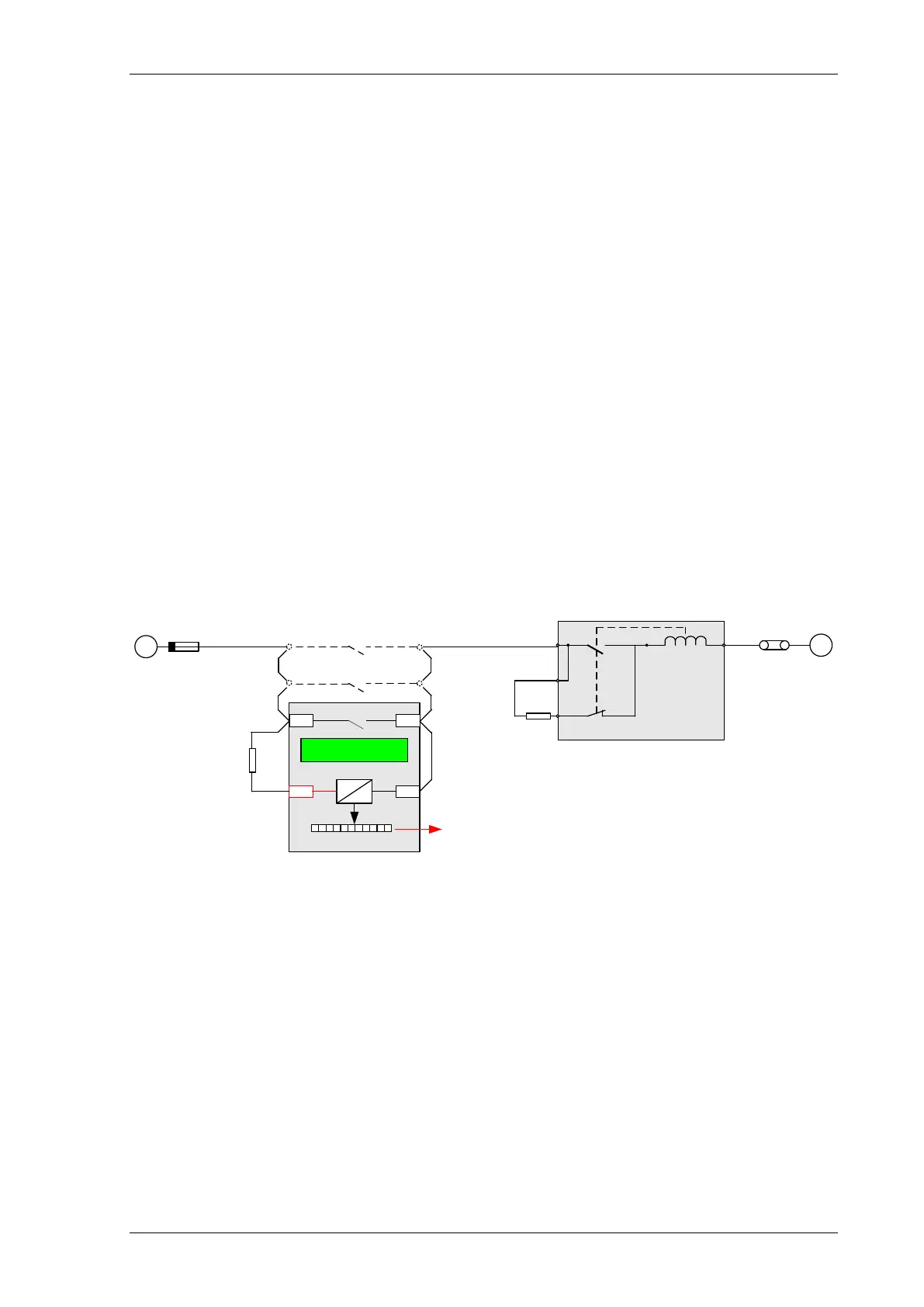
TRIP CCT n FAIL
Figure 5.4-1 Trip Circuit Supervision Scheme 1 (H5)
Scheme 1 provides full Trip supervision with the circuit breaker Open or Closed.
Where a ‘Hand Reset’ Trip contact is used measures must be taken to inhibit alarm indications after a CB trip.

 Loading...


