7SR11 & 7SR12 Description Of Operation
©2017 Siemens Protection Devices Limited Chapter 1 Page 83 of 88
Fault records provide a summary of the relay status at the time of trip, i.e. the element that issued the trip, any
elements that were picked up, the fault type, LED indications, date and time. The Max Fault Rec. Time setting
sets the time period from fault trigger during which the operation of any LEDs is recorded.
The relay can be set to automatically display the fault record on the LCD when a fault occurs by enabling the
SYSTEM CONFIG> Trip Alert setting. When the trip alert is enabled the fault record will be displayed until the
fault is removed.
With the Trip Alert setting enabled the user will have to press the TEST/RESET► button three times in order to
return to the home screen after a trip has occurred. The user will then have to press the TEST/RESET► button a
further time (four in total) to reset the relay.
1. After a trip occurs the Trip Alert displays the time and date of the trip. The user then presses the
TEST/RESET► button.
2. The fault type is then displayed with the date the fault occurred. The fascia prompts the user to press the
TEST/RESET► button to view the details of this fault.
3. The information regarding the fault is then displayed. The user then presses the TEST/RESET► button
to return to the home screen.
4. Pressing the TEST/RESET► button one further time will reset the relay.
With the Trip Alert setting disabled the user only has to press the trip reset button once to reset the relay.
When examined together the event records and the fault records will detail the full sequence of events leading to
a trip.
Fault records are stored in a rolling buffer, with the oldest faults overwritten. The fault storage can be cleared with
the DATA STORAGE/Fault Storage>Clear Faults setting or from Reydisp.
6.5.6 ENERGY STORAGE - 7SR12
The measured Power is continuously integrated (over a one-second window) to produce 4 Energy quantities:
• Active Export Energy (W)
• Active Import Energy (W)
• Reactive Export Energy (VAr)
• Reactive Import Energy (VAr)
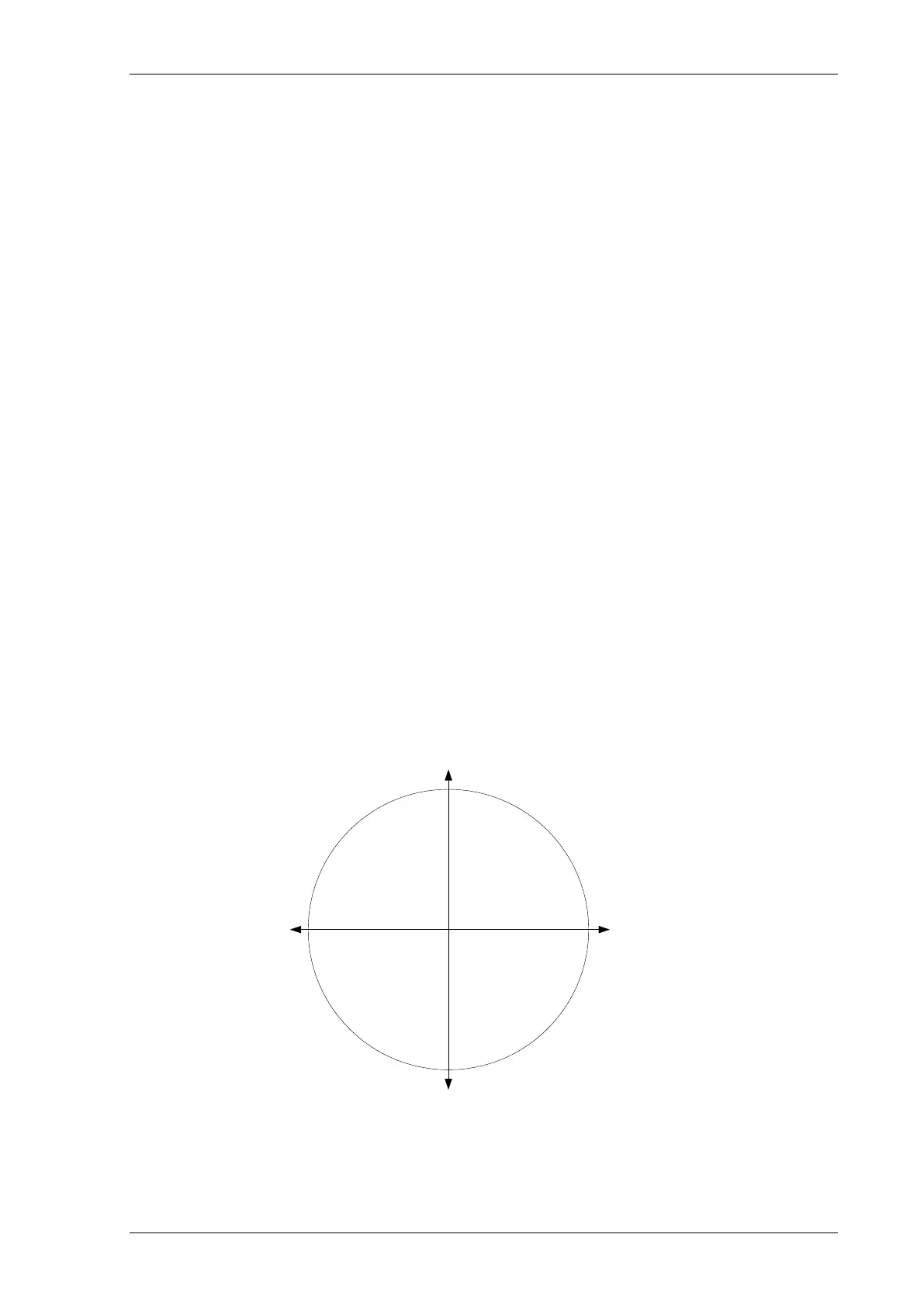
The Direction of Energy transfer is set by: SYSTEM CONFIG> Export Power/Lag VAr. With both Export Power
(W) and Lag VAr (VAr) set to be +ve, the Direction of Energy transfer will follow the IEC convention, as shown in
the figure.
ACTIVE ENERGY IMPORT
(watts reverse
)
IEC CONVENTION : -ve watts
REACTIVE ENERGY IMPORT
(vars reverse
)
IEC CONVENTION : -ve vars
REACTIVE ENERGY EXPORT
(vars forward)
IEC CONVENTION : +ve vars
POWER FACTOR LEADING
ACTIVE (W) EXPORT
REACTIVE (VAr) IMPORT
POWER FACTOR LAGGING
ACTIVE (
W) IMPORT
REACTIVE (VAr
) IMPORT
POWER FACTOR LEADING
ACTIVE (W) IMPORT
REACTIVE (VAr) EXPORT
0°
+90
°
180
°
-90
°
POWER FACTOR LAGGING
ACTIVE (W) EXPORT
REACTIVE (VAr) EXPORT
ACTIVE ENERGY EXPORT
(watts forward)
IEC CONVENTION : +ve watts
Figure 6-1 Energy Direction Convention

 Loading...


