7SR11 & 7SR12 Commissioning and Maintenance Guide
©2017 Siemens Protection Devices Limited Chapter 6 Page 58 of 72
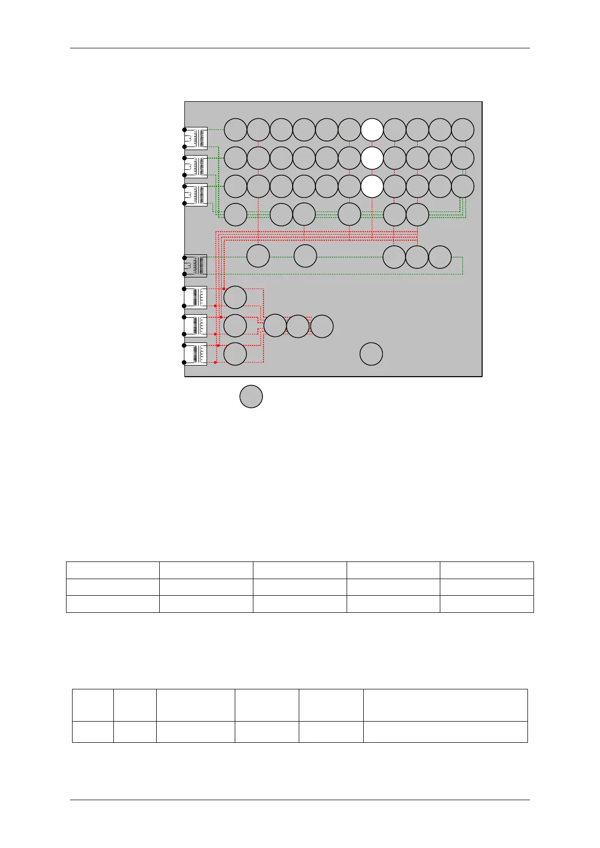
2.18 Power Factor (55)
7SR12
46
BC
46
NPS
(x2)
37
(x2)
49
50
BF
51V
V
L1
(V
A
)
V
L2
(V
B
)
V
L3
(V
C
)
I
L1
(I
A
)
81
HBL
2
37
(x2)
49
50
BF
51V
I
L2
(I
B
)
81
HBL
2
37
(x2)
49
50
BF
51V
I
L3
(I
C
)
81
HBL
2
I
4
(I
G
)
74
T/
CCS
NOTE: The use of some
functions are mutually exclusive
67/
50
(x4)
67/
51
(x4)
67/
50N
(x4)
67/
50
(x4)
67/
50
(x4)
67/
51
(x4)
67/
51
(x4)
67/
51N
(x4)
67/
50 G/
SEF
67/
51 G/
SEF
27
59
(x4)
27
59
(x4)
27
59
(x4)
47
(x2)
79
Optional
59N
(x2)
Note:
Example shows
Voltage Config =
Van, Vbn, Vcn
60
CTS
60
VTS
50BF
51c
51c
51c
64H
81
(x4)
32
(x2)
32
(x2)
32
(x2)
55
(x2)
55
(x2)
55
(x2)
50
AFD
(x2)
50
AFD
(x2)
50
AFD
(x2)
32S
Figure 2-21 Power Factor
Voltage Inputs: V
L1
(V
A
), V
L2
(V
B
), V
L3
(V
C
)
Current Inputs: I
L1
(I
A
), I
L2
(I
B
), I
L3
(I
C
),
Disable: 49
Map Pickup LED: 55-n - Self Reset
Apply balanced 3 phase rated voltage and current. Increase current phase angle until the LED assigned to ’55-n’
is lit. Record this angle in the table below. Decrease the angle until the LED resets. Record the angle.
If the element is set as 55-n U/C Guarded, the setting can be tested by applying the test current at a level below
the 55-n U/C Guard Setting at a power in the operate range. Increase the current until the relay operates.
Setting
Used for test
Current
Current

 Loading...


