7SR11 & 7SR12 Commissioning and Maintenance Guide
©2017 Siemens Protection Devices Limited Chapter 6 Page 17 of 72
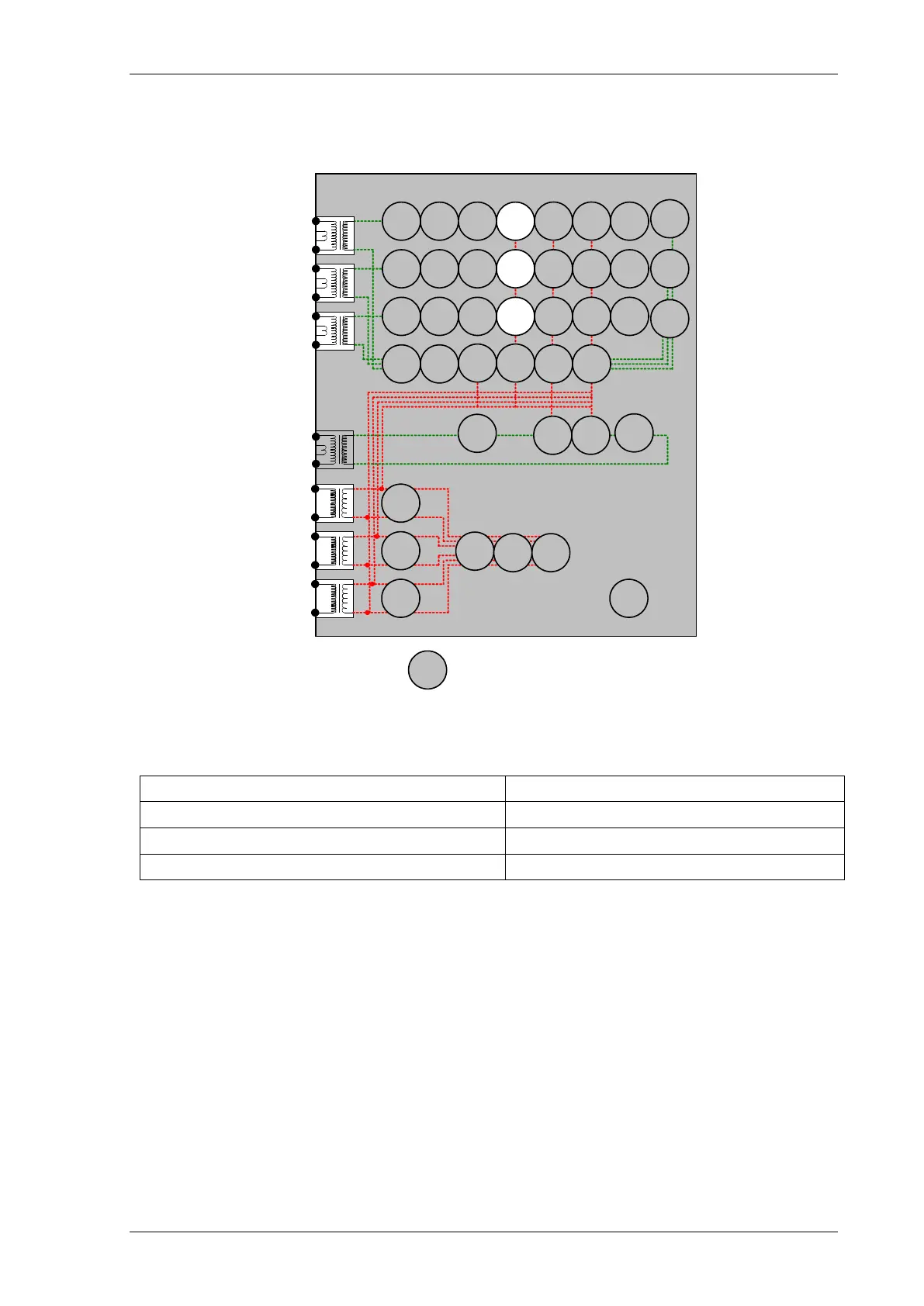
2.3 Voltage Controlled Overcurrent (51V)
Figure 2-3 Voltage Controlled Overcurrent
Voltage Inputs: V
L1
(V
A
), V
L2
(V
B
), V
L3
(V
C
)
Current Inputs: I
L1
(I
A
), I
L2
(I
B
), I
L3
(I
C
),
Disable: 51C, 46, 37, 49, 50CBF, 79
Map Pickup LED: 51-n/50-n - Self Reset
Shaped Phase Overcurrent elements 51-n should be tested for pick-up and timing before this function is tested.
The General Pickup LED can be used to assess operation of this function if other functions are disabled or if the
setting allocating General Pickup is temporarily modified.
Apply nominal 3 phase balanced voltage. Apply 3 phase balanced current at a level below the normal 51-n setting
but above the effective 51V-n setting. Ensure that the thermal rating of the relay is not exceeded. Gradually
reduce the voltage until the a-b voltage is less than the Voltage setting. Pickup LED operation can be used to
confirm the Voltage setting. If the 51V-n current setting is above the continuous rating of the relay an alternative
procedure should be used, apply test current in short duration shots with applied voltage being gradually reduced
for each subsequent shot
7
SR12
46
BC
46
NPS
(
x2
)
37
(
x2
)
49
50
BF
51
V
V
L
1
(
V
A
)
V
L
2
(V
B
)
V
L
3
(V
C
)
I
L
1
(I
A
)
81
HBL
2
37
(
x2
)
49
50
BF
51
V
I
L2
(I
B
)
81
HBL
2
37
(x
2
)
49
50
BF
51
V
I
L3
(
I
C
)
81
HBL
2
I
4
(
I
G
)
74
T/
CCS
NOTE:
The use of some
functions are mutually exclusive
67/
50
(x
4)
67
/
51
(
x4
)
67
/
50N
(
x4
)
67/
50
(
x
4)
67/
50
(
x
4)
67/
51
(
x
4)
67/
51
(
x4
)
67
/
51N
(
x4
)
67/
50G
(
x4
)
67/
51G
(
x4
)
27
59
(
x4)
27
59
(
x4
)
27
59
(x4
)
79
Optional
Note:
Example shows
Voltage Config =
Van,
Vbn, Vcn
60
CTS
60
VTS
50
BF
51c
51
c
51c
64
H
47
(
x2
)
59
N
(x
2)
81
(x
4)

 Loading...


