7SR11 & 7SR12 Commissioning and Maintenance Guide
©2017 Siemens Protection Devices Limited Chapter 6 Page 44 of 72
2.13 Thermal Overload (49)
7
SR12
46
BC
46
NPS
(
x
2)
37
(
x
2
)
49
50
BF
51
V
V
L1
(V
A
)
V
L
2
(V
B
)
V
L3
(
V
C
)
I
L
1
(
I
A
)
81
HBL
2
37
(
x
2
)
49
50
BF
51
V
I
L
2
(
I
B
)
81
HBL
2
37
(
x2
)
49
50
BF
51
V
I
L
3
(
I
C
)
81
HBL
2
I
4
(
I
G
)
74
T/
CCS
NOTE
: The use of some
functions are mutually exclusive
67
/
50
(
x
4
)
67/
51
(
x
4
)
67
/
50
N
(
x4
)
67
/
50
(
x
4)
67
/
50
(x
4
)
67
/
51
(
x4
)
67
/
51
(x
4
)
67
/
51N
(x
4
)
67/
50
SEF
67
/
51
SEF
27
59
(
x
4)
27
59
(
x4
)
27
59
(x
4
)
47
(x
2
)
79
Optional
59
N
(x
2)
Note:
Example shows
Voltage Config
=
Van
, Vbn
, Vcn
60
CTS
60
VTS
50BF
51c
51
c
51
c
64H
81
(x
4)
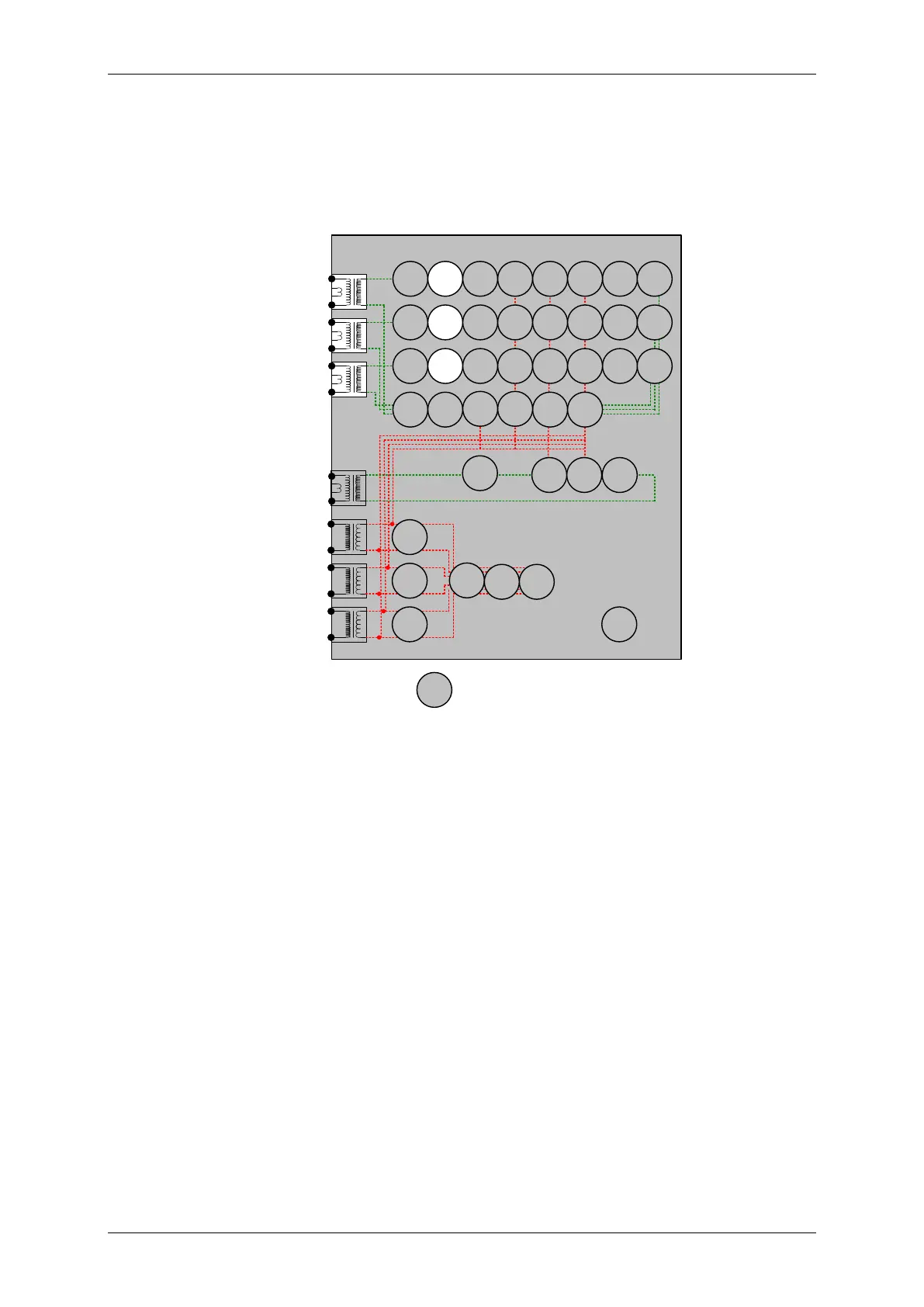
Figure 2-14 Thermal Overload
Voltage Inputs: n/a
Current Inputs: I
L1
(I
A
), I
L2
(I
B
), I
L3
(I
C
),
Disable: 51, 50, 37, 50CBF
Map Pickup LED: 49Alarm
The current can be applied from a 3P balanced supply or phase by phase from a 1P supply. Alternatively the 3
phase current inputs can be connected in series and injected simultaneously from a single 1P source.
The Thermal Overload Setting and Time Constant Setting can be considered together to calculate the operating
time for a particular applied current.
The following table lists operate times for a range of Time Constant Settings for an applied current of 2x the
Thermal Overload setting. Ensure that the thermal rating of the relay is not exceeded during this test.

 Loading...


