7SR11 & 7SR12 Description Of Operation
©2017 Siemens Protection Devices Limited Chapter 1 Page 39 of 88
3.3 Current Protection: Measured Earth Fault (67G, 51G, 50G)
The earth current is measured directly via a dedicated current analogue input, IL4.
All measured earth fault elements have a common setting to measure either fundamental frequency RMS or True
RMS current:
True RMS current: 50 Measurement = RMS, 51 Measurement = RMS
Fundamental Frequency RMS current: 50 Measurement = Fundamental, 51 Measurement =
Fundamental
3.3.1 DIRECTIONAL CONTROL OF MEASURED EARTH FAULT PROTECTION (67G) – 7SR12
The directional element produces forward and reverse outputs for use with measured earth fault elements. These
outputs can be mapped as controls to each shaped and instantaneous element.
If a protection element is set as non-directional then it will operate independently of the output of the directional
detector. However, if a protection element is programmed for forward directional mode then operation will occur
only for a fault lying within the forward operate zone. Conversely, if a protection element is programmed for
reverse directional mode then operation will occur only for a fault lying within the reverse operate zone. Typically
the forward direction is defined as being ‘away’ from the busbar or towards the protected zone.
The Characteristic angle is the phase angle by which the polarising voltage must be adjusted such that the
directional detector gives maximum sensitivity in the forward operate zone when the current is in phase with it.
The reverse operate zone is the mirror image of the forward zone.
The measured directional earth fault elements use zero phase sequence (ZPS) polarising.
Voltage polarisation is achieved for the earth-fault elements by comparison of the appropriate current with its
equivalent voltage:
I
0
~ V
0
The characteristic angle can be user programmed to any angle between -95° and +95° using the 67G Char
Angle setting. The voltage is the reference phasor (V
ref
) and the 67G Char Angle setting is added to this to adjust
the forward and reverse zones.
The centre of the forward zone is set by (V
ref
Angle + 67G Char Angle) and should be set to correspond with I
fault
Angle for maximum sensitivity e.g.
For fault current of -15° (I lagging V by 15°) a 67G Char Angle of -15° is required for maximum
sensitivity, OR
For fault current of -45° (I lagging V by 45°) a 67G Char Angle of -45° is required for maximum
sensitivity.
MINIMUM POLARISING VOLTAGE
The 67G Minimum Voltage setting defines the minimum polarising voltage level. Where the measured polarising
voltage is below this level no directional output is given and. Operation of protection elements set as directional
will be inhibited. This prevents mal-operation under fuse failure/MCB tripped conditions where noise voltages can
be present.
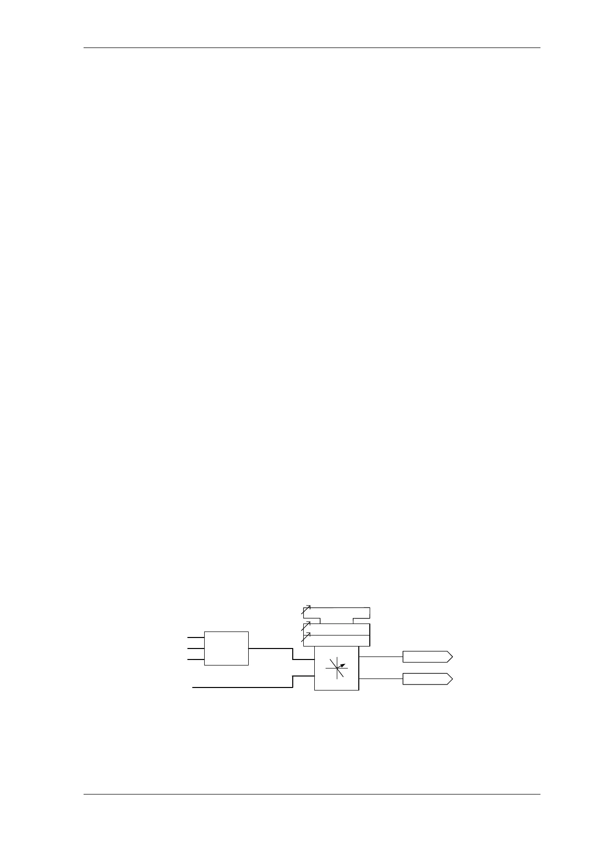
fwd
rev
67G
67G Min. Voltage
67G Charact. Angle
67G Fwd
67G Rev
V
0
VL1
VL2
VL3
Sequence
Filters
IL4
Figure 3-8 Logic Diagram: Measured Directional Earth Fault Protection

 Loading...


