FS20 Marine Fire Detection Control Panel
Siemens Industry, Inc. A6V10519176_enUS_b
Building Technologies Division
18.4 Pin Assignments for Releasing Module
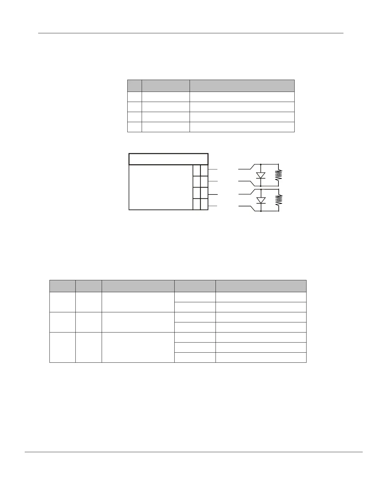
18.4.1 X5 plug connection for releasing relay output
4 REL_CIR1 (+) Relay output for releasing 1
3 REL_CIR1 (-) Relay output for releasing 1
2 REL_CIR2 (+) Relay output for releasing 2
1 REL_CIR2 (-) Relay output for releasing 2
Admissible cable cross-section: 12…18 AWG, unshielded
+
-
3
4
+
- 1
2
X5
REL_CIR2
REL_CIR2
REL_CIR1
REL_CIR1
*
REL_EOL
*
REL_EOL
*REL-EOL: Terminating resistor 24 kΩ and diode (Siemens part
number 500-696359)
18.5 Indicators
18.5.1 LED indicators
H1 Green Status of releasing circuit 1 Off Releasing circuit 1 inactive
On Releasing circuit 1 activated
H2 Green Status of releasing circuit 2 Off Releasing circuit 2 inactive
On Releasing circuit 2 activated
H3 Green Status of processor Off (steady) Processor is not running
Flashing Processor is running
On (steady) Processor is not running