FS20 Marine Fire Detection Control Panel
Siemens Industry, Inc. A6V10519176_enUS_b
Building Technologies Division
X801 Bell Follower Terminal Block
1 BF (-) Input from external fire control panel.
The return feed from the external control unit’s NAC circuit connects here.
2 BF (+) Input from external fire control panel.
The active positive output from the external control unit’s NAC circuit
connects here.
Admissible cable cross-section: 1 x 12-18 AWG or 2 x 16-18 AWG
12.4 Auxiliary 24VDC Output
The Auxiliary output DC 24 Volt with a maximum output current of 1.5 A; the output
can be used for devices such as door holders, DACT, or RDT. The circuit is power
limited and is protected against a direct shorted output. The output is power limited
and supervised for over current. To configure the output to shut down during AC loss
to conserve the battery, you must configure the system with the Engineering tool.
If the output is configured to turn off the battery, then the output is used for
supplementary purposes only.
12.4.1 Wiring Specs
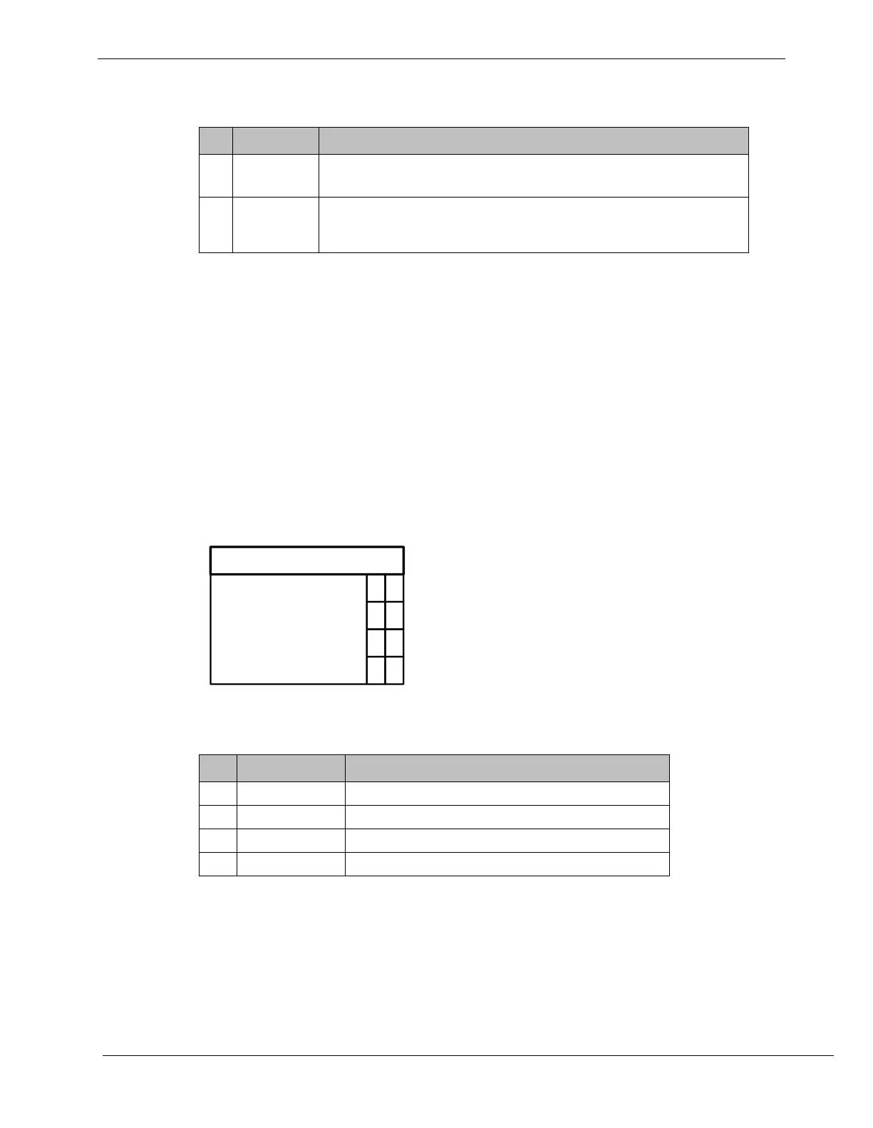
X1001
1
AUX
+
AUX
2
3
4
-
+
-
AUX
AUX
12.4.2 X1001 Auxiliary Output Terminal Block
1 AUX (+) Positive feed for Aux circuit (DC +24 V)
2 AUX (-) Return feed Aux circuit
3 AUX (+) Positive feed for Aux circuit (DC +24 V)
4 AUX (-) Return feed Aux circuit
Admissible cable cross-section: 1 x 12-18 AWG or 2 x 16-18 AWG