FS20 Marine Fire Detection Control Panel
Siemens Industry, Inc. A6V10519176_enUS_b
Building Technologies Division
12.2 Notification Appliance Circuits
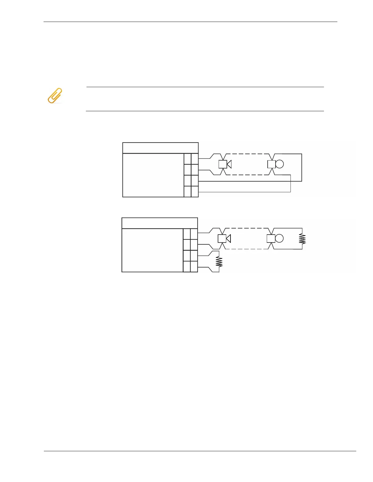
The following wiring diagrams displays the process to connect notification devices to
the circuit, either as class A (style Z) or class B (style Y) circuit. For class A, no end-of-
line resistor is required. It is built into the circuit.
To ensure proper functioning, the jumpers must be set correctly for class A/B
selection.
Polarity shown is in activated condition.
Notification appliance circuit supervised and power limited.
X601
1
NAC1-2
+
NAC1-2
2
3
4
-
+
-
NAC1-1
NAC1-1
+
+
-
-
X601: Class A (style Z) supervised output connection
X601
1
NAC1-2
+
NAC1-2
2
3
4
-
+
-
NAC1-1
NAC1-1
+
+
-
-
*
EOL
EOL
X601: Class B (style Y) supervised output connection
* EOL resistance must be connected during non-use.
EOL resistance: 2.4 kΩ, 0.5 W
See also
X602 Jumper – DEGRADED MODE ENABLE/DISABLE for NAC 1 class A or NAC 1-1
class B
X603 Jumper – DEGRADED MODE ENABLE/DISABLE for NAC 1-2 class B
X604, X605, X606 Jumper – NAC 1 class A/B