FS20 Marine Fire Detection Control Panel
Siemens Industry, Inc. A6V10519176_enUS_b
Building Technologies Division
Connections X3 Connection for ribbon cable to display
X4 Connection for ribbon cable to display
X5 Connection plug for supply and 'NET_OUT' circuit output
X6 Connection plug for input supply and 'NET_IN' line input
X11 Connection for key switch
Switch S1 DIP switch, 8-pole, for address setting and other functions
S2 Reset key
Indicators H1…H29 LED indicators, front
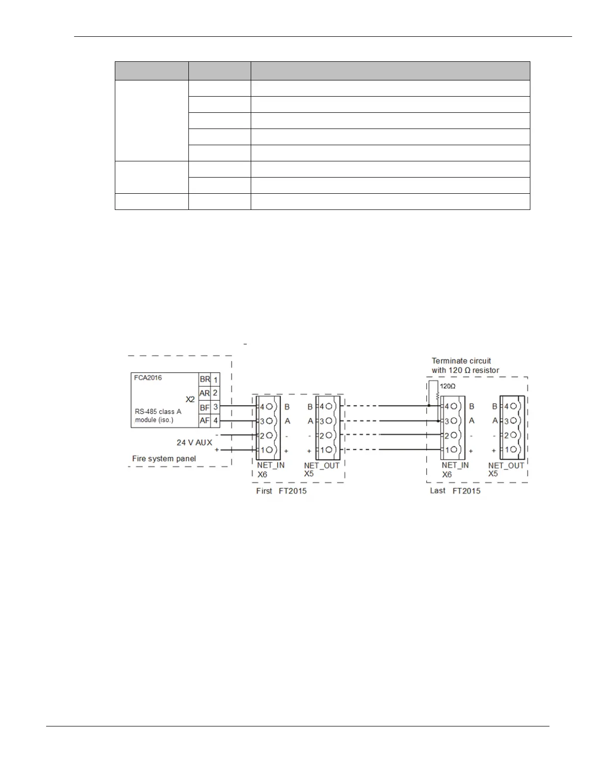
19.4 Wiring
The circuit must not be terminated on the side of the RS-485 class ‘A’ module,
because the RS-485 class ‘A’ module has integrated terminating resistors.
When wiring as a class ‘B’ circuit, the circuit on the last device must be terminated
with a 120 Ω resistor.
Wiring from the Remote Terminal to the RS-485 Circuit as A Class ‘B’
Circuit
FT2015 class B, style 4 wiring