FS20 Marine Fire Detection Control Panel
Siemens Industry, Inc. A6V10519176_enUS_b
Building Technologies Division
11.3 Configuration Input Power and Battery
The periphery board system functions are configured by the jumper. The
jumper settings are described in the following sections.
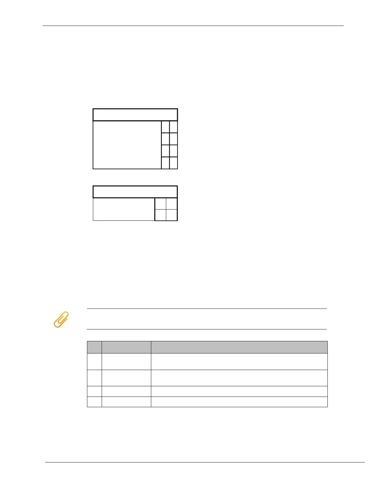
11.3.1 Wiring Specs
X303
BAT - - 2
BAT + + 1
11.3.2 X301 Terminal Block – Power Supply 1
Verify the AC is disconnected. Link power supply (170W) connection to X301.
X301 must always have a power supply connected.
Do not connect AC or batteries until all jumpers and modules are configured and
connected in the system. Once everything is installed and connected, connect
the AC first and then the batteries.
To power down the system, first disconnect the batteries, then the AC power.
1 BROO (White) AC Brown Out. Signals when the mains connection drops
below AC 102 V.
2 PSSI (Green) Power supply status indication. Used by the periphery board
to know the health of the power supply.
3 GND (Black) Return (ground)
4 +24 V (Red) DC +24 V system supply
Admissible cable cross-section: 1 x 12…18 AWG or 2 x 16…18 AWG