FS20 Marine Fire Detection Control Panel
Siemens Industry, Inc. A6V10519176_enUS_b
Building Technologies Division
15.2 Installation
The network module (SAFEDLINK) FN2001-U1 must be installed in the left slot (X13)
(main module slot).
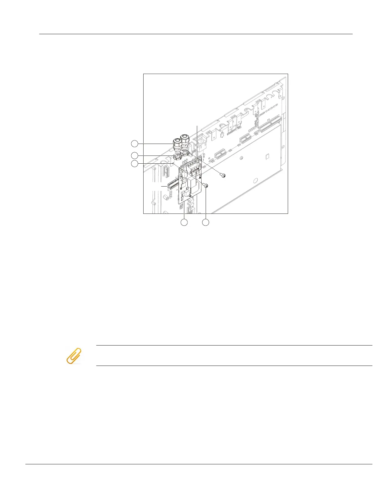
Installing the network module (SAFEDLINK) FN2001-U1
1 Fastening tabs on operating unit
2 Nut for screwed cable gland (2 per module)
1
3 Cable gland (2 per module)
1
4 2x fixing screw
5 Network module (SAFEDLINK) on X13 (master module)
X3 FCnet/SAFEDLINK connection terminal
X13 Connection terminal on Operating Unit & Mainboard
1
When using shielded cables, the cable glands are needed to secure the
shielding.
Ensure you install the network module (SAFEDLINK) in the correct position (plug X13) during installation.
1. When shielded cables are used, mount the two cable glands (3) with the
nuts (2) on the flange between the fastening tabs (1).
2. Plug the network module (SAFEDLINK) (5) into the connector X13 as shown.
3. Fasten the network module to the fastening tabs (1) using the two fixing
screws (4).
4. Check that the network module is secured correctly in order to prevent open
circuits.
5. Wire up the system bus SAFEDLINK according to the pin assignment.