FS20 Marine Fire Detection Control Panel
Siemens Industry, Inc. A6V10519176_enUS_b
Building Technologies Division
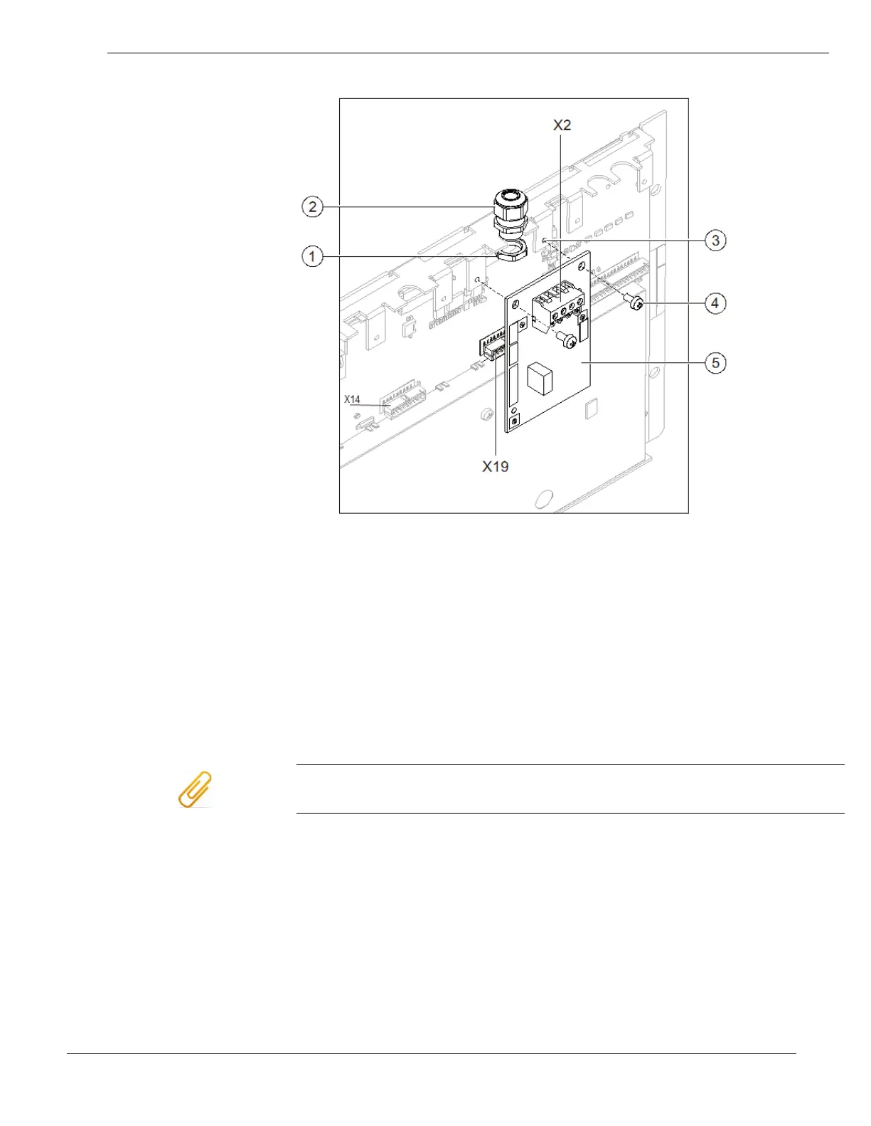
Installation of the serial modules
1 Nut for screwed cable gland
2 Screwed cable gland
3 Mounting links on support plate
4 2x fixing screw
5 RS-485 class A module (iso.)
X2 Connection terminal on RS-485 module
X19 (X14) Slot for RS-485 module
Cable glands do not have to be fitted for wiring inside the enclosure. When using
shielded cables, the cable glands are needed to secure the shielding.
1. Install the cable gland (2) with the nut (1) on the flange between the
fastening tabs (3).
2. Plug the serial module (5) into the corresponding connector (X14 or
X19).
3. Fasten the serial module to the fastening tabs (3) using the two
screws (4).
4. Wire the serial module with the appropriate assemblies according to
the pin assignment.