6.8 Block icon for redundant components
Introduction
Information for a redundant component is displayed in different ways:
● In one block icon
● In several block icons
You can use the block icon to open the associated faceplate.
Block icons
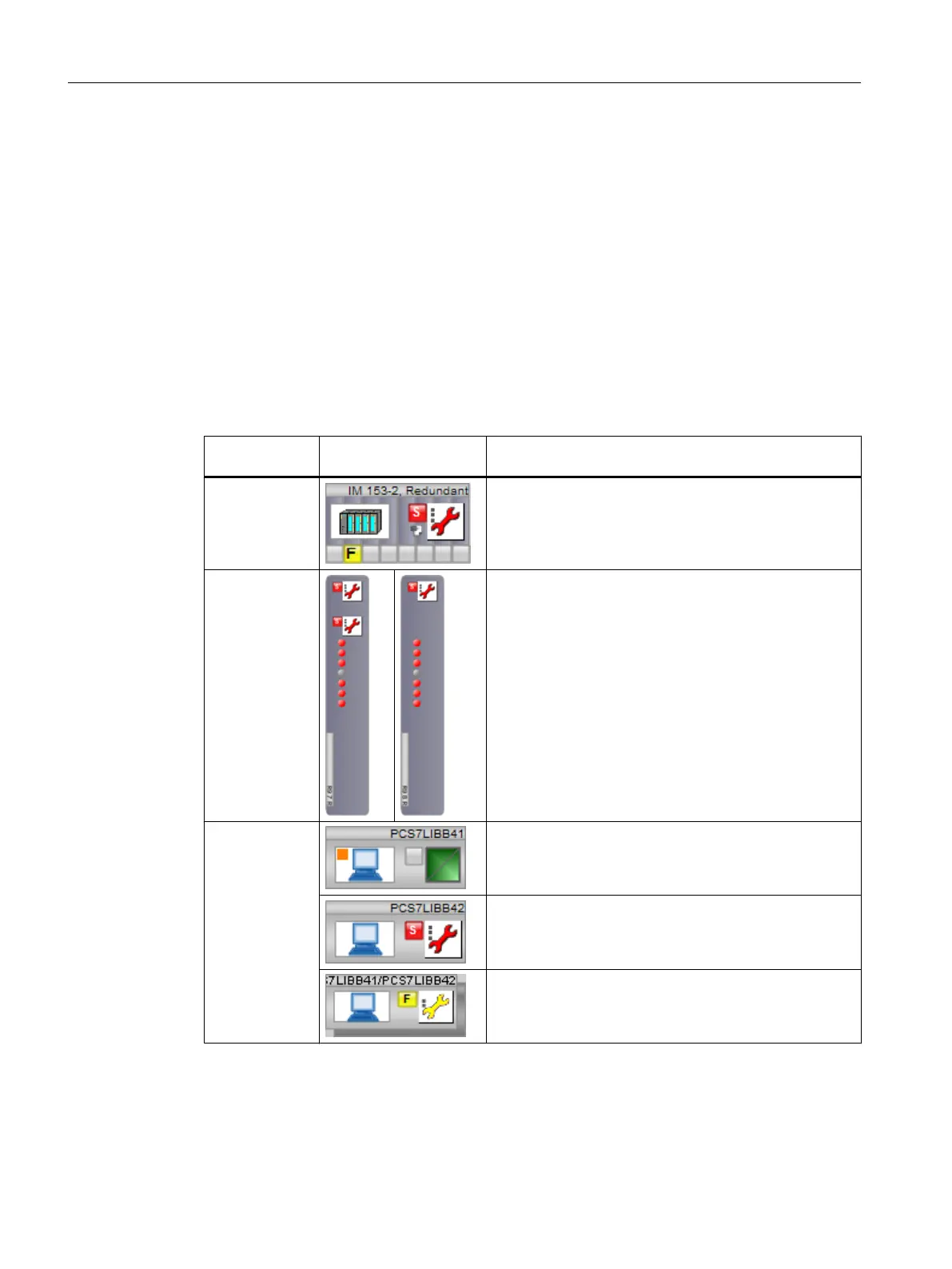
The following table shows the possible types of display:
Redundant
component
Display Explanation
IM 153-2 The redundancy state is displayed for the component and
its partner in a diagnostic icon.
I/O
module
The maintenance state of each component is indicated in
the assigned diagnostic icon (top diagnostic icon).
A redundancy object is also displayed for the component
with the lower address.
The redundancy state is displayed in the diagnostic icon
of the redundancy object.
PC objects The role of master is indicated by an orange square.
The maintenance state of its partner is indicated in the
diagnostic icon.
The redundancy state is indicated in the diagnostic icon
in the redundancy object.
Additional information
You can find additional information in the sections "Block icon (Page 119)" and "Maintenance
status of redundant components (Page 126)".
Operator control and monitoring
6.8 Block icon for redundant components
Maintenance Station
122 Function Manual, 03/2016, A5E36187641-AA

 Loading...


