6.11.2 Screen window title and header
6.11.2.1 Displays and operator controls
Introduction
The control bar always has the same structure. The appropriate icons are displayed depending
on the component type and on the configuration.
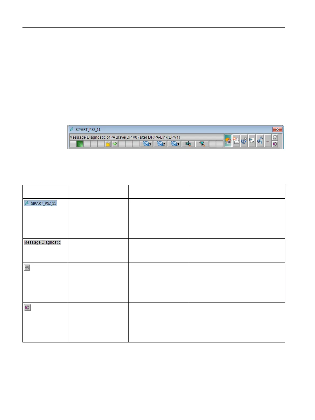
The following figure shows an example of the display:
Display
The following table provides an overview:
Icon Name Display for components
from the area
Function/remark
Screen window title
● PC stations
● Network objects
● AS/system
● Field devices
● User objects
Display of the local ID
You can find additional information about
the local ID in the section "Origin of the iden‐
tification data (Page 183)".
Block comment
● AS/system
● Field devices
● User objects
Display of the block comment
The local ID is displayed in the tooltip.
Pin faceplate
● PC stations
● Network objects
● AS/system
● Field devices
● User objects
Pins the faceplate on the user interface
This allows you to change to another picture
or area without closing the faceplate.
Return
● PC stations
● Network objects
● AS/system
● Field devices
● User objects
Calls the process picture
After a picture change you see the process
picture in which the faceplate was called and
pinned.
Operator control and monitoring
6.11 Faceplate
Maintenance Station
132 Function Manual, 03/2016, A5E36187641-AA

 Loading...


