6.2 Layout of the user interface
User interface in the process control
The user interface is structured in the same way as the Operator System interface. It is divided
into 3 areas:
● Overview area (Page 91)
The overview area is displayed permanently. Its group displays for the various plant areas
and the message line provide an overview of the entire plant.
Display and operator control in the overview area is the same as display and operator
control in an OS.
If deviations exist, the document points this out.
● Working area (Page 94)
In the working area, the overview screen, the area overview screens and the diagnostic
screens of the individual components are displayed for the diagnostics area.
● Button area (Page 94)
The button area is displayed permanently. It comprises several button sets between which
the maintenance engineer (operator of the "Diagnostics" area) can switch.
The keys in the button sets are operated in the same way as the keys in an OS.
If deviations exist, the document points this out.
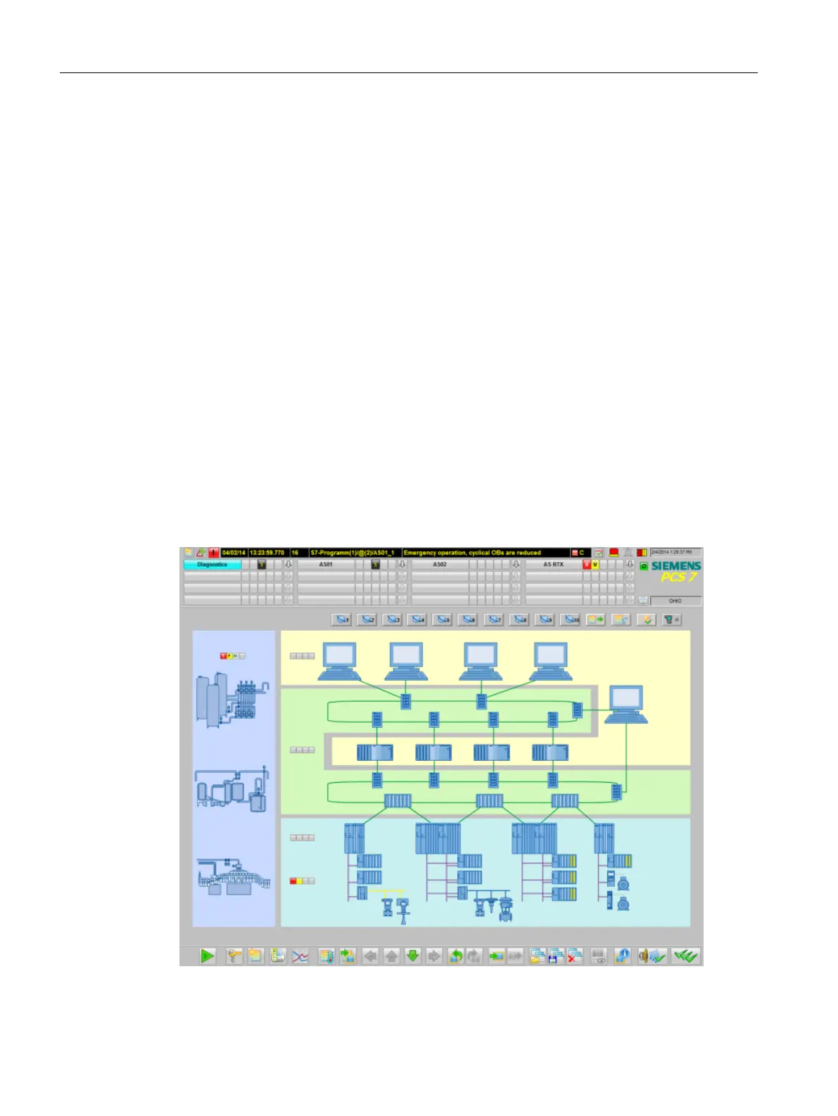
The following figure shows an example of the user interface:
Operator control and monitoring
6.2 Layout of the user interface
Maintenance Station
90 Function Manual, 03/2016, A5E36187641-AA

 Loading...


