Overview
Up to 18 binary states of an IPC are displayed in this view.
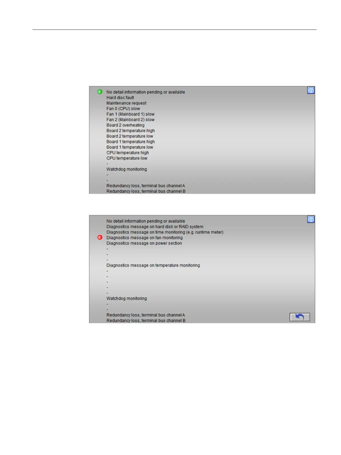
● The following figure shows an example of the view for a component IPC with the profile
V1.3:
● The following figure shows an example of the view for a component IPC with the profile
V1.4 or higher:
The redundancy loss of channel A/B is only indicated in the case of a redundant connection
to the terminal bus with Softnet IE/RNA in combination with the IPC Profile 1.5.
As soon as one of the two terminal bus cables is removed, this is visualized with a "red"
state display.
These displays are not controlled with Intel Teaming.
Operator control and monitoring
6.11 Faceplate
Maintenance Station
Function Manual, 03/2016, A5E36187641-AA 153

 Loading...


