Result
The MCC chart is created in the project.
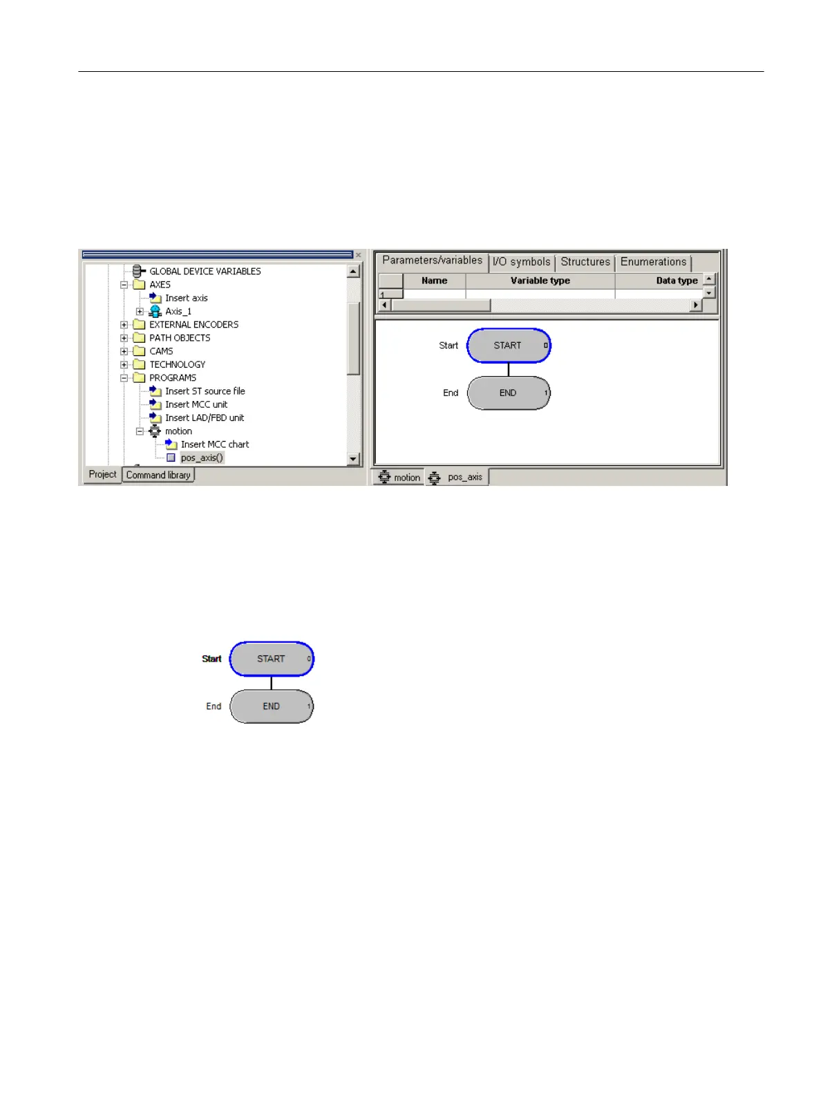
● The created MCC chart pos_axis appears in the PROGRAMS folder below the motion
source.
● The MCC editor is opened in the working area of the workbench. The start and end nodes
are already pre-defined. You can start MCC programming.
Figure 6-30 MCC chart "pos_axis" inserted
6.6.2.4 Using MCC command blocks
Every newly created MCC chart already contains a start and an end node.
Figure 6-31 MCC chart, start/end nodes
You insert the MCC command blocks between these. The commands are processed in the
direction from the start to the end node.
The MCC commands are available to you via:
● MCC editor toolbar
● MCC chart > Paste menu command
● Context menu of the command block
Configuring/parameterizing
6.6 Programming the SIMOTION application
SIMOTION SCOUT
Configuration Manual, 11/2016 117