Filtering the display by operating state or CPU name
The selection field in the header of the Target device column offers the following filter values:
Table 7-2 Filter values in the Target device column
Filter value Filter result
All All CPUs are displayed, regardless of whether they are in online or offline
mode
Online Only CPUs that are in online mode are displayed.
User-definable The field can be edited, thus enabling filtering according to parts of names.
Up to five user-defined filters remain for selection.
Operating states
State column: Shows the state of the CPUs in text form and via static LEDs.
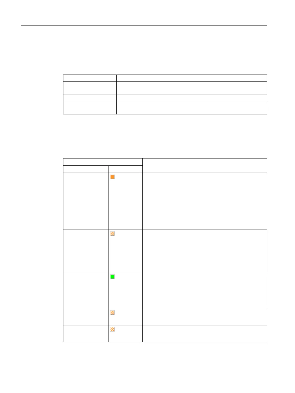
Table 7-3 Operating states of a SIMOTION device
Operating state Description
Text LED
STOP
(orange)
● Technology objects inactive (enables deleted, no axis
motion)
● User program is not executed
● Loading a user program is possible
● All system services are active (communication, etc.)
● All analog and digital outputs set to 0
● The I/O modules (signal modules) are in the safe state
(SIMOTION D)
STOP U
(orange/white)
● Technology objects are active
● Technology objects can execute jobs for testing and
commissioning functions.
● Otherwise identical to STOP operating state
● STOP U means stop user program
● User program is not executed
RUN
(green)
● Technology objects are active
● Execution of the user programs assigned to the execution
system
● Loading a user program is possible
● Process image of the inputs and outputs is read or written
STOP
(orange/white)
● All tasks shut down, operating system stopped, real-time
clock continues to run.
STARTUP
(orange/white)
● The display only appears if the state persists longer than
1 second, or in the event of a fault.
Target system
7.3 Controlling the operating mode with SIMOTION SCOUT
SIMOTION SCOUT
156 Configuration Manual, 11/2016