Programming and Operating Manual (Milling)
6FC5398-4DP10-0BA1, 01/2014
11
Control elements on the MCP
Elements on the MCP (Machine Control Panel) front
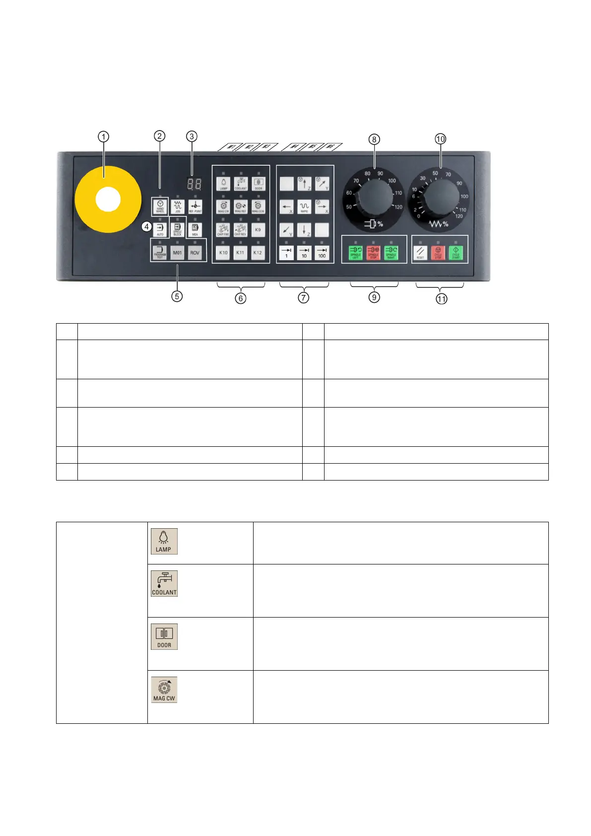
The following illustration uses a horizontal MCP as an example to show control elements available on the MCP:
①
Reserved hole for emergency stop button
⑦
②
Controls the axis movement with external handwheels
⑧
(unavailable for the vertical MCP with reserved
handwheel slot)
③
Displays the current tool number
⑨
④
⑩
Traverses the selected axis at the specified feedrate
override
⑤
⑪
Keys for program start, stop, and reset
⑥
*
* For more information, refer to the table below.
User-defined keys
Pressing this in any operating mode switches on/off the lamp.
LED lit: The lamp is switched on.
LED unlit: The lamp is switched off.
Pressing this key in any operating mode switches on/off the coolant
supply.
LED lit: The coolant supply is switched on.
LED unlit: The coolant supply is switched off.
When all axes and the spindle stop operation, pressing this key unlocks
the safety door.
LED lit: The safety door is unlocked.
LED unlit: The safety door is locked.
Pressing this key rotates the magazine clockwise (active only in JOG
mode).
LED lit: The magazine rotates clockwise.
LED unlit: The magazine stops clockwise rotation.
 Loading...


