Programming and Operating Manual (Milling)
6FC5398-4DP10-0BA1, 01/2014
53
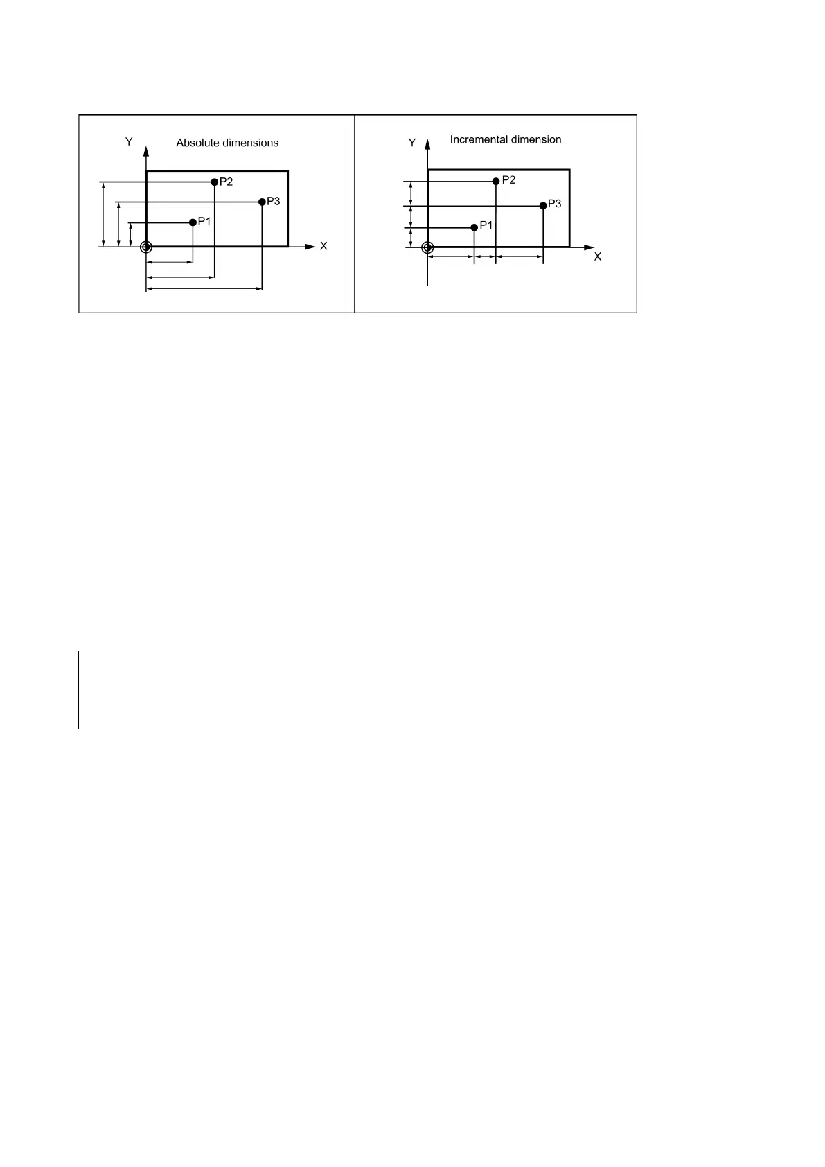
See the following illustration for different dimensioning types in the drawing:
Absolute dimensioning G90
With absolute dimensioning, the dimensioning data refers to the
zero of the coordinate system currently active
(workpiece
or current workpiece coordinate system or machine coordinate system). This is dependent on which offsets are currently
active: programmable, settable, or no offsets.
Upon program start, G90 is active for
and remains active until it is deselected in a subsequent block by G91
(incremental dimensioning data) (modally active).
Incremental dimensioning G91
With incremental dimensioning, the numerical value of the path information corresponds to the
axis path to be traversed
.
The leading sign indicates the
.
G91 applies to all axes and can be deselected in a subsequent block via G90 (absolute dimensioning).
Specification with =AC(...), =IC(...)
After the end point coordinate, write an equality sign. The value must be specified in round brackets.
Absolute dimensions are also possible for circle center points using =AC(...). Otherwise, the reference point for the circle
center is the circle starting point.
; X-dimensions remain absolute, incremental Z dimension
; Switch-over to incremental dimensioning
; X-remains incremental dimensioning, Z-absolute
Dimensions in metric units and inches: G71, G70, G710, G700
Functionality
If workpiece dimensions that deviate from the base system settings of the control system are present (inch or mm), the
dimensions can be entered directly in the program. The required conversion into the base system is performed by the control
system.
G70 ; Inch dimensions
G71 ' Metric dimensions
G700 ; Inch dimensions, also for feedrate F
G710 ; Metric dimensions, also for feedrate F

 Loading...


