Programming and Operating Manual (Milling)
38 6FC5398-4DP10-0BA1, 01/2014
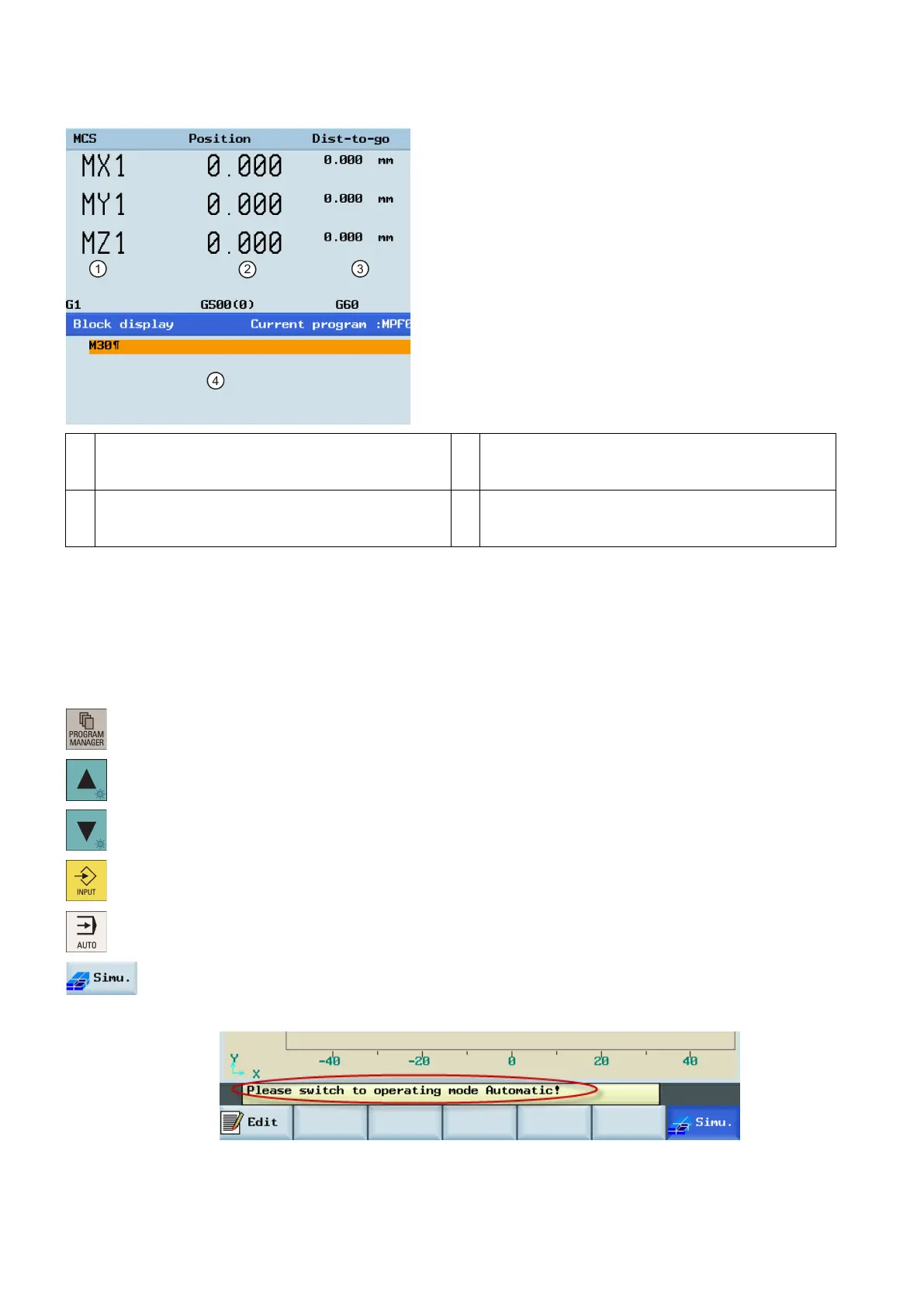
①
Displays the axes that exist in the machine coordinate
system (MCS), workpiece coordinate system (WCS), or
relative coordinate system(REL).
③
Displays the remaining distance for the axes to
traverse.
②
Displays the current position of the axes in the selected
coordinate system.
④
Displays seven subsequent blocks of the currently
active part program. The display of one block is limited
to the width of the window.
Performing the simulation
Functionality
By using the broken-line graphics, the programmed tool path can be traced. Before the automatic machining, you need to
perform the simulation to check whether the tool moves in the right way.
Select the desired operating area.
Select a part program for simulation.
Press this key to open the program.
Press this softkey to open the program simulation window, and the program control mode PRT is
automatically activated.
If the control system is not in the correct operating mode, a message will appear at the bottom of
the screen as follows. If this message appears, repeat Step 4.
 Loading...


