Programming and Operating Manual (Milling)
80 6FC5398-4DP10-0BA1, 01/2014
The drilling depth is specified by specifying one of the axes X, Y or Z; the thread pitch is specified via the relevant I, J or K.
G33 remains active until canceled by another instruction from this G group (G0, G1, G2, G3...).
Right-hand or left-hand thread
Right-hand or left-hand thread is set with the rotation direction of the spindle (M3 right (CW), M4 left (CCW) - see Section
"Spindle movements (Page 87)"). To do this, the rotation value must be programmed under address S or a rotation speed
must be set.
A complete cycle of tapping with compensating chuck is provided by the standard cycle CYCLE840.
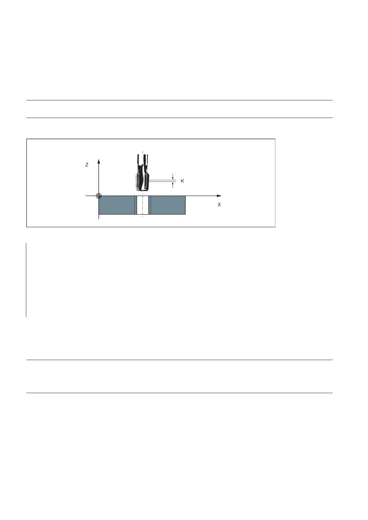
See the following illustration for tapping using G33:
; pitch as per table: 0.8 mm/rev., hole already
N10 G54 G0 G90 X10 Y10 Z5 S600 M3 ; Approach starting point, clockwise spindle
; Tapping, end point -25 mm
; Retraction, counter-clockwise spindle rotation
With G33 threads, the velocity of the axis for the thread lengths is determined on the basis of the spindle speed and the
thread pitch. The
feedrate F is not relevant
. It is, however, stored. However, the maximum axis velocity (rapid traverse)
defined in the machine data can not be exceeded. This will result in an alarm.
● The spindle speed override switch should remain unchanged for thread machining.
● The feedrate override switch has no meaning in this block.
Tapping with compensating chuck: G63
Functionality
G63 can be used for tapping with compensating chuck. The programmed feedrate F must match with the spindle speed S
(programmed under the address "S" or specified speed) and with the thread pitch of the drill:
F [mm/min] = S [rpm] x thread pitch [mm/rev.]
 Loading...


