Programming and Operating Manual (Milling)
246 6FC5398-4DP10-0BA1, 01/2014
The position of the coordinate system is displayed in the graphics window.
An element was selected using the cursor keys.
Pressing the following softkey allows you to enlarge the image section of the selected element:
Specifying contour elements in polar coordinates
Functionality
The description about defining the coordinates of contour elements applies to the specification of positional data in the
Cartesian coordinate system. Alternatively, you have the option to define positions using polar coordinates.
When programming contours, you can define a pole at any time prior to using polar coordinates for the first time.
Programmed polar coordinates subsequently refer to this pole. The pole is modal and can be re-defined at any time. It is
always entered in absolute Cartesian coordinates. The contour calculator converts values entered as polar coordinates into
Cartesian coordinates. Positions can be programmed in polar coordinates only
a pole has been specified. The pole
input does not generate a code for the NC program.
The polar coordinates are valid in the level selected with G17 to G19.
The pole is a contour element that can be edited, which itself does not contribute to the contour. It
can be entered when the starting point of the contour is defined or anywhere within the contour. The
pole cannot be created before the starting point of the contour.
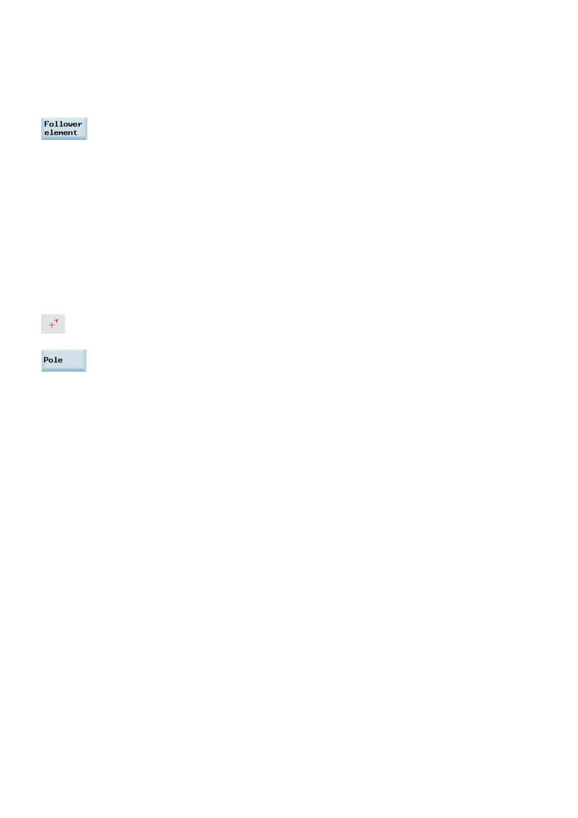
This softkey allows you to specify a pole and can only be entered in absolute Cartesian
coordinates. This softkey is also present in the starting point screen. This enables the pole to be
entered at the start of a contour, so that the first contour element can be entered in polar
coordinates.
If the straight line that was generated with close contour is linked to the start element of the contour with a radius or chamfer,
the radius or chamfer must be specified explicitly as follows:
● Close contour, input key, enter radius/chamfer, accept element. The result then corresponds exactly to what would occur
if the closing element were to be entered with the radius or chamfer.
Close contour can only be used for entering contour elements in
if the starting point of the contour was
set to polar and the
is still valid when the contour is closed.
Input switchover: Cartesian/polar
The following contour elements can be entered optionally in polar coordinates only after a pole has been defined, whether
this was done at the outset or later in the process:
● Circular arcs,
● Straight lines (horizontal, vertical, any direction)
To switchover between Cartesian and polar coordinates, additional toggle fields are displayed in the programming windows
for the contour elements of oblique lines and circular arcs.
A toggle field is not displayed if no pole exists. Input fields and display fields are then only available for Cartesian values.
Absolute/incremental input
Absolute and incremental polar coordinates can be input for "polar/Cartesian". The input fields and display fields are labeled
and
.
Absolute polar coordinates are defined by an absolute distance to the pole that is always positive and an angle in the range
of 0° ... +/- 360°. When absolute dimensions are specified, the angular reference is based on a horizontal axis of the working
plane, e.g. X axis with G17. The positive direction of rotation runs counter-clockwise.
If there are several input poles, the definitive pole is always the
before the input or edited element.
Incremental polar coordinates relate to both the definitive pole and the end point of the preceding element.

 Loading...


