Programming and Operating Manual (Milling)
6FC5398-4DP10-0BA1, 01/2014
131
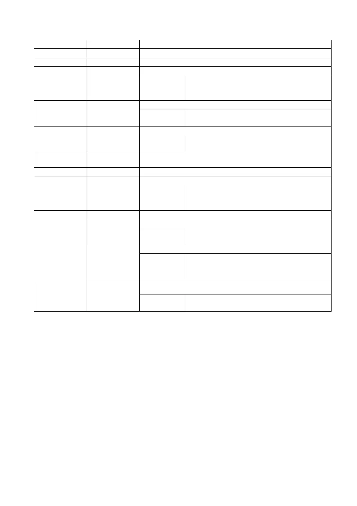
FDEP REAL First drilling depth (absolute)
FDPR REAL First drilling depth relative to the reference plane (enter without sign)
DAM REAL Amount of degression (enter without sign)
Values: >0: degression as value
<0: degression factor
=0: no degression
DTB REAL Dwell time at drilling depth (chip breakage)
Values: >0: in seconds
<0: in revolutions
DTS REAL Dwell time at starting point and for chip removal
Values: >0: in seconds
<0: in revolutions
FRF REAL Feedrate factor for the first drilling depth (enter without sign) Range of values:
0.001 ... 1
VARI INT Machining type: Chip breakage=0, Chip removal=1
AXN INT Tool axis
Values: 1: 1st geometrical axis
2: 2nd geometrical axis
3: 3rd geometrical axis
MDEP REAL Minimum drilling depth (only in connection with degression factor)
VRT REAL Variable retraction value for chip breakage (VARI=0)
Values: >0: if traction value
=0: retraction value 1mm set
DTD REAL Dwell time at final drilling depth
Values: >0: in seconds
<0: in revolutions
=0: value same as DTB
DIS1 REAL Programmable limit distance for reinsertion in the drill hole (for chip removal
VARI=1)
Values: >0: programmable value applies
=0: automatic calculation
The tool drills at the programmed spindle speed and feedrate to the entered final drilling depth.
Deep hole drilling is performed with a depth infeed of a maximum definable depth executed several times, increasing
gradually until the final drilling depth is reached.
The drill can either be retracted to the reference plane + safety clearance after every infeed depth for swarf removal or
retracted in each case by 1 mm for chip breaking.
Sequence
Position reached prior to cycle start:
The drilling position is the position in the two axes of the selected plane.
The cycle creates the following sequence:
Deep hole drilling with chip removal (VARI=1)
● Approach of the reference plane brought forward by the safety clearance by using G0
 Loading...


