Programming and Operating Manual (Milling)
188 6FC5398-4DP10-0BA1, 01/2014
FFD REAL Feedrate for depth infeed
FFP1 REAL Feedrate for surface machining
MID REAL Maximum infeed depth for one infeed (enter without sign)
CDIR INT Milling direction for machining the slot
Values: 2 (for G2), 3 (for G3)
FAL REAL Finishing allowance at the slot edge (enter without sign)
VARI INT Machining type
Values: 0 = complete machining, 1 = roughing, 2 = finishing
MIDF REAL Maximum infeed depth for finishing
FFP2 REAL Feedrate for finishing
SSF REAL Speed when finishing
FALD REAL Finishing allowance at the slot base (enter without sign)
STA2 REAL Maximum insertion angle for oscillation movement
DP1 REAL Insertion depth per revolution for helix (incremental)
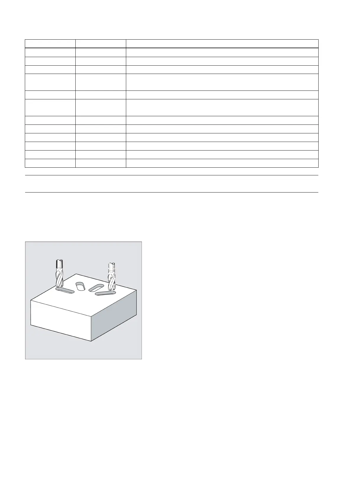
The cycle requires a milling cutter with an "end tooth cutting across center" (DIN844).
The cycle SLOT1 is a combined roughing-finishing cycle.
Use this cycle to machine slots arranged on a circle. The longitudinal axis of the slots is aligned radially. In contrast to the
long hole, a value is defined for the slot width.
Sequence
Position reached prior to cycle start:
The starting position can be any position from which each of the slots can be approached without collision.
 Loading...


