Programming and Operating Manual (Milling)
244 6FC5398-4DP10-0BA1, 01/2014
①
Absolute (abs) / incremental (inc) end position in X or Y
direction.
④
You can specify a side-based parallel contour
allowance. It is displayed as an allowance in the
graphics window.
②
Transition element to the next contour is a chamfer
(CHR) or a radius (RND). CHR=0 or RND=0 means no
transition element.
⑤
The contour chain which displays the start point and
programmed contour elements. The current position in
the chain is color-highlighted.
③
Input field for suppl
ementary comments, such as F1000
feedrate values, H or M functions. If comments are
entered as text, they must always be started with a
semicolon ";".
⑥
The graphics window which displays the progress of the
contour as you configure the parameters for the
elements.
The following additional parameters are displayed after you press this softkey:
L Length of the straight line
α1 Pitch angle with reference to Y axis
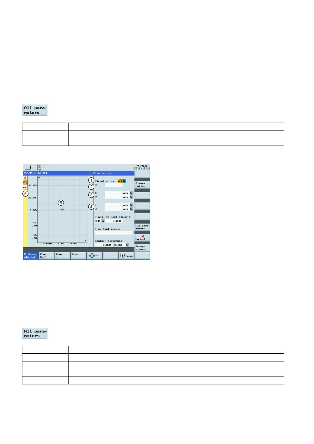
Parameters for programming circular arcs
①
Direction of rotation of the circular arc: clockwise or
counter-clockwise.
④
Absolute (abs) / incremental (inc) positions of circle
center point in Y (I) and X (K) directions.
②
Radius of circle.
⑤
The contour chain which displays the start point and
programmed contour elements. The current position in
the chain is color-highlighted.
③
Absolute (abs) / incremental (inc) end positions in X and
Y directions.
⑥
The graphics window which displays the progress of the
contour as you configure the parameters
elements.
The following additional parameters are displayed after you press this softkey:
α1 Starting angle with reference to Y axis
α2 Angle to preceding element; tangential transition: α2=0
β1 End angle with reference to Y axis
β2 Angle of aperture of circle

 Loading...


