The current value is set at address 1607 67N-TOC PICKUP. The minimum appearing ground fault current is
most relevant for this setting.
The corresponding element time multiplication factor for an IEC characteristic is set at address 1608 67N-TOC
T-DIAL and in address 1609 67N-TOC T-DIAL for an ANSI characteristic. This has to be coordinated with
the system grading coordination chart for directional tripping. For ground currents with grounded network,
you can mostly set up a separate grading coordination chart with shorter delay times.
The time multiplier can also be set to ∞. After pickup the element will then not trip. Pickup, however, will be
signaled. If the 67N-TOC element is not required at all, address 116 67N/67N-TOC should be set to Defi-
nite Time during protection function configuration (see Section 2.1.1).
Inrush Restraint
When applying the protection device to transformers where high inrush currents are to be expected, the
7SJ80 can make use of an inrush restraint function for the directional overcurrent elements 67-1 PICKUP,
67-TOC PICKUP, 67N-1 PICKUP and 67N-TOC PICKUP as well as the non-directional overcurrent
elements. The inrush restraint option is enabled or disabled in 2201 INRUSH REST. (in the settings option
non-directional time overcurrent protection). The characteristic values of the inrush restraint are already listed
in the section discussing the non-directional time overcurrent (Section 2.2.11 Setting Notes).
Manual Close Mode (phases, ground)
When a circuit breaker is closed onto a faulted line, a high speed trip by the circuit breaker is often desired. For
overcurrent or high-set element the delay may be bypassed via a Manual Close pulse, thus resulting in instan-
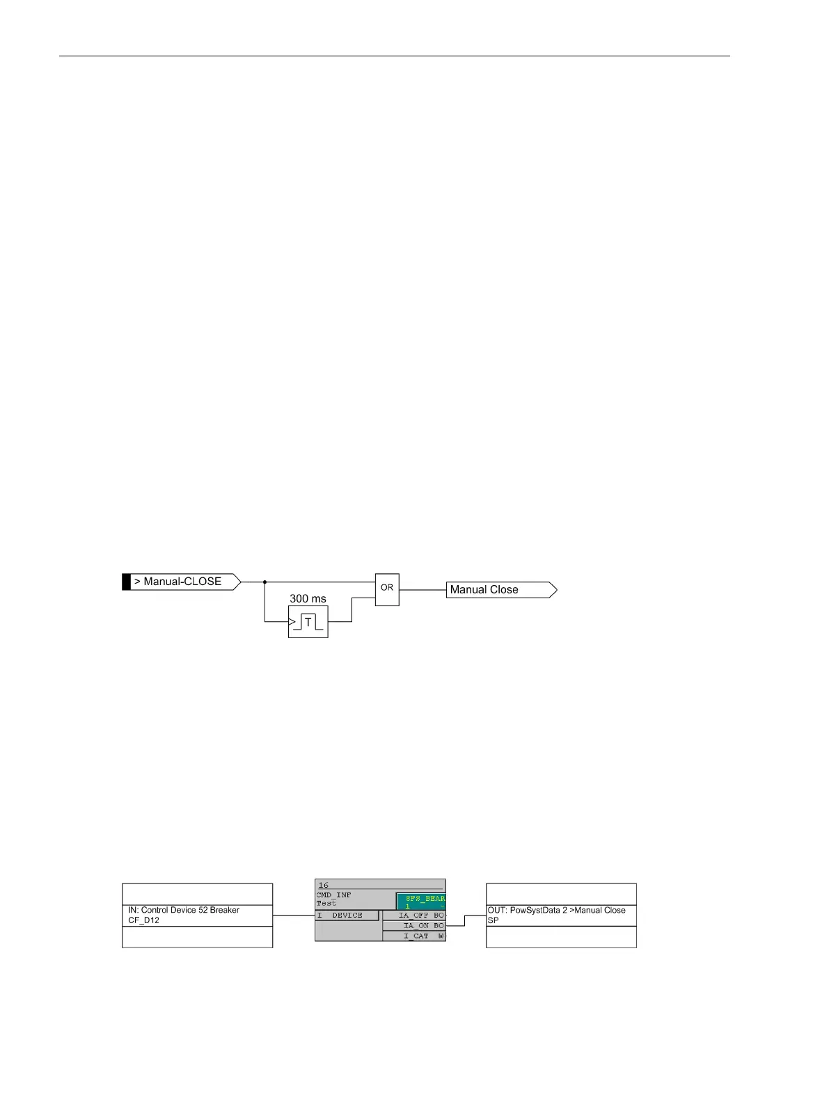
taneous tripping. The internal "Manual close" signal is built from the binary input signal
>Manual Close
(no.
356). The internal "Manual close" signal remains active as long as the binary input signal
>Manual Close
is
active, but at least for 300 ms (see the following logic diagram). To enable the device to react properly on
occurrence of a fault in the phase elements after manual close, address 1513 MANUAL CLOSE has to be set
accordingly. Accordingly, address 1613 MANUAL CLOSE is considered for the ground path address. Thus, the
user determines for both elements, the phase and the ground element, what pickup value is active with what
delay when the circuit breaker is closed manually.
[lo_7sj6-hand-ein, 1, en_US]
Figure 2-32 Manual close feature
External Control Switch
If the manual close signal is not from the 7SJ80 device, that is, neither sent via the built-in operator interface
nor via a serial port but directly from a control acknowledgment switch, this signal must be passed to a 7SJ80
binary input, and configured accordingly (
>Manual Close
), so that the element selected for MANUAL
CLOSE can become effective. Inactive means that all elements (phase and ground) operate with the config-
ured trip times even with manual close.
Internal Control Function
The manual closing information must be allocated via CFC (interlocking task-level) using the CMD_Information
block, if the internal control function is used.
[handein-260602-kn, 1, en_US]
Figure 2-33 Example for the generation of a manual close signal using the internal control function
Functions
2.3 Directional Overcurrent Protection 67, 67N
100 SIPROTEC 4, 7SJ80, Manual
E50417-G1140-C343-A8, Edition 12.2017

 Loading...


