[7sj80-erdfehler-iee-cos-sin-20061206, 1, en_US]
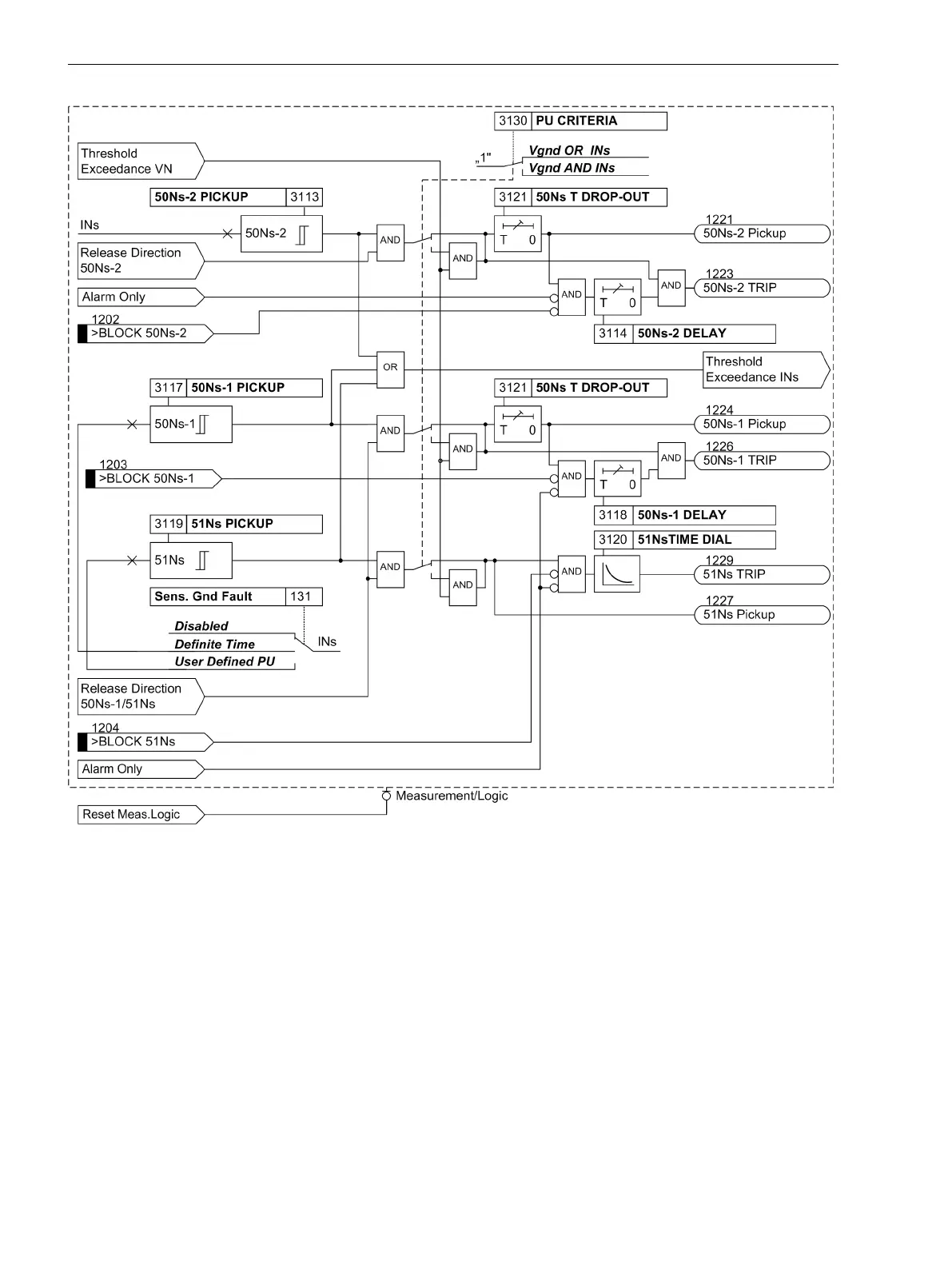
Figure 2-72
Logic diagram of the Ι
Ns
elements for cos-ϕ -/sin-ϕ measurement
Ground Fault Detection for V0/I0-ϕ Measurement
Voltage Element
The voltage element relies on a pickup initiated by the displacement voltage V
0
or 3 · V
0
. Additionally, the
faulty phase is determined. The displacement voltage V
0
can be directly applied to the device, or the summa-
tion voltage 3 · V
0
can be calculated according to the connection type of the voltage transformer (see also
Parameter 213 VT Connect. 3ph in Section 2.1.3 Power System Data 1). When setting Van, Vbn, Vcn,
the calculation of the summation voltage 3 · V
0
is based on the three phase-to–Ground voltages. The three
voltage inputs must therefore be connected to the voltage transformers in a grounded-wye configuration.
When setting Vab, Vbc, VGnd, the three phase-to-Ground voltages of both connected phase-to-phase
voltages and the connected displacement voltage are calculated. If the device is only provided with phase-to-
phase voltages, it is not possible to calculate a displacement voltage from them. In this case, the direction
cannot be determined.
2.12.2
Functions
2.12 Ground Fault Protection 64, 67N(s), 50N(s), 51N(s)
178 SIPROTEC 4, 7SJ80, Manual
E50417-G1140-C343-A8, Edition 12.2017
 Loading...


