Inverting Power Measured Values/Metered Values
The directional values (power, power factor, work and related min., max., mean and setpoint values), calcu-
lated in the operational measured values, are usually defined a positive in the direction of the protected
object. This requires that the connection polarity for the entire device was configured accordingly in the
P.System Data 1 (compare also "Polarity of the Current Transformers", address 201). But it is also possible
to make different settings for the "forward" direction" for the protection functions and the positive direction
for the power etc., e.g. to have the active power supply (from the line to the busbar) displayed positively. To
do so, set address 1108 P,Q sign to reversed. If the setting is not reversed (default), the positive
direction for the power etc. corresponds to the "forward" direction for the protection functions. Section
4 Technical Data provides a detailed list of the values in question.
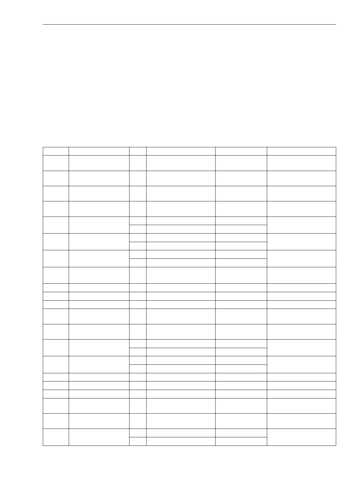
Settings
The table indicates region-specific presettings. Column C (configuration) indicates the corresponding secon-
dary nominal current of the current transformer.
Addr. Parameter C Setting Options Default Setting Comments
1101 FullScaleVolt. 0.10 .. 800.00 kV 20.00 kV Measurem:FullScale-
Voltage(Equipm.rating)
1102 FullScaleCurr. 10 .. 50000 A 400 A Measurem:FullScaleCur-
rent(Equipm.rating)
1103 RE/RL -0.33 .. 7.00 1.00 Zero seq. compensating
factor RE/RL
1104 XE/XL -0.33 .. 7.00 1.00 Zero seq. compensating
factor XE/XL
1105 x' 1A 0.0050 .. 15.0000 Ω/mi 0.2420 Ω/mi feeder reactance per mile:
x'
5A 0.0010 .. 3.0000 Ω/mi 0.0484 Ω/mi
1106 x' 1A 0.0050 .. 9.5000 Ω/km 0.1500 Ω/km feeder reactance per km: x'
5A 0.0010 .. 1.9000 Ω/km 0.0300 Ω/km
1107 I MOTOR START 1A 0.40 .. 10.00 A 2.50 A Motor Start Current (Block
49, Start 48)
5A 2.00 .. 50.00 A 12.50 A
1108 P,Q sign not reversed
reversed
not reversed P,Q operational measured
values sign
1109 Line angle 10 .. 89 ° 85 ° Line angle
1110 Line length 0.1 .. 1000.0 km 100.0 km Line length in kilometer
1111 Line length 0.1 .. 650.0 Miles 62.1 Miles Line length in miles
6001 S1: RE/RL -0.33 .. 7.00 1.00 S1: Zero seq. compen-
sating factor RE/RL
6002 S1: XE/XL -0.33 .. 7.00 1.00 S1: Zero seq. compen-
sating factor XE/XL
6003 S1: x' 1A 0.0050 .. 15.0000 Ω/mi 0.2420 Ω/mi S1: feeder reactance per
mile: x'
5A 0.0010 .. 3.0000 Ω/mi 0.0484 Ω/mi
6004 S1: x' 1A 0.0050 .. 9.5000 Ω/km 0.1500 Ω/km S1: feeder reactance per
km: x'
5A 0.0010 .. 1.9000 Ω/km 0.0300 Ω/km
6005 S1: Line angle 10 .. 89 ° 85 ° S1: Line angle
6006 S1: Line length 0.1 .. 650.0 Miles 62.1 Miles S1: Line length in miles
6007 S1: Line length 0.1 .. 1000.0 km 100.0 km S1: Line length in kilometer
6011 S2: RE/RL -0.33 .. 7.00 1.00 S2: Zero seq. compen-
sating factor RE/RL
6012 S2: XE/XL -0.33 .. 7.00 1.00 S2: Zero seq. compen-
sating factor XE/XL
6013 S2: x' 1A 0.0050 .. 15.0000 Ω/mi 0.2420 Ω/mi S2: feeder reactance per
mile: x'
5A 0.0010 .. 3.0000 Ω/mi 0.0484 Ω/mi
2.1.6.3
Functions
2.1 General
SIPROTEC 4, 7SJ80, Manual 53
E50417-G1140-C343-A8, Edition 12.2017

 Loading...


