No. Information Type of
Informa-
tion
Comments
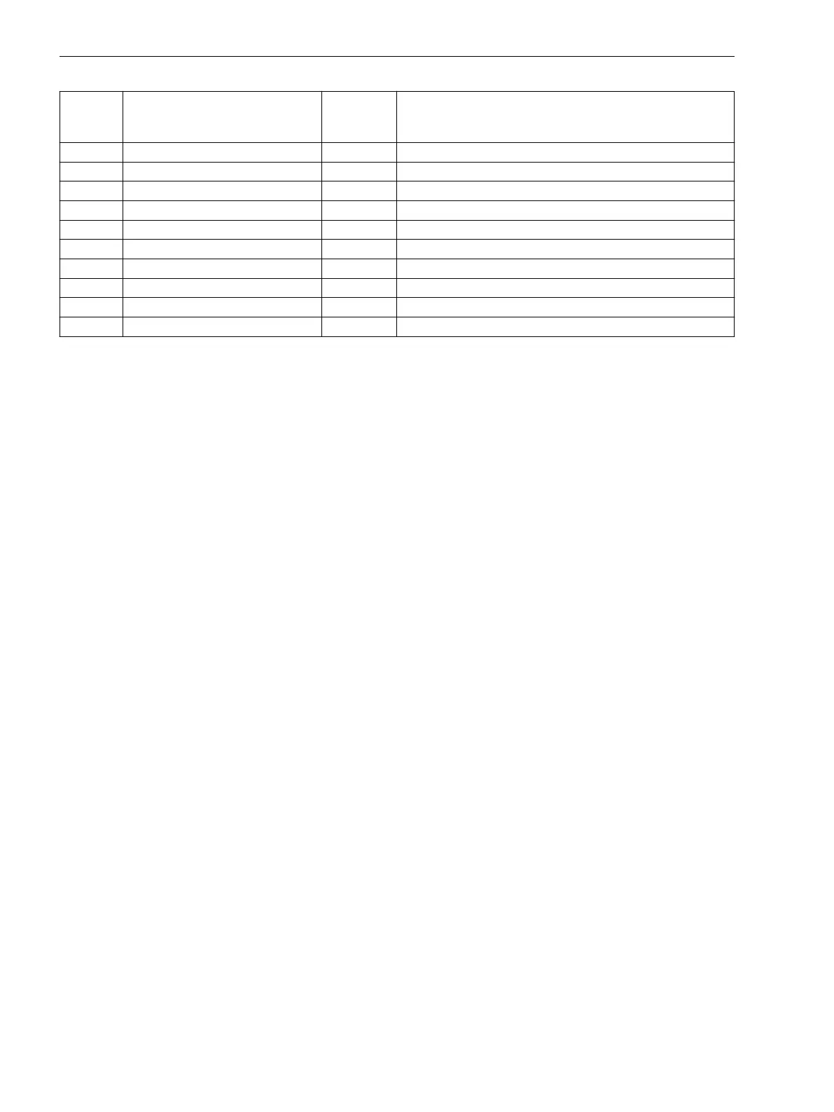
175 Fail Ph. Seq. I OUT Failure: Phase Sequence Current
176 Fail Ph. Seq. V OUT Failure: Phase Sequence Voltage
197 MeasSup OFF OUT Measurement Supervision is switched OFF
253 VT brk. wire OUT Failure VT circuit: broken wire
255 Fail VT circuit OUT Failure VT circuit
256 VT b.w. 1 pole OUT Failure VT circuit: 1 pole broken wire
257 VT b.w. 2 pole OUT Failure VT circuit: 2 pole broken wire
258 VT b.w. 3 pole OUT Failure VT circuit: 3 pole broken wire
6509 >FAIL:FEEDER VT SP >Failure: Feeder VT
6510 >FAIL: BUS VT SP >Failure: Busbar VT
Trip Circuit Supervision 74TC
Devices 7SJ80 are equipped with an integrated trip circuit supervision. Depending on the number of available
binary inputs (not connected to a common potential), supervision with one or two binary inputs can be
selected. If the allocation of the required binary inputs does not match the selected supervision type, then a
message to this effect is generated (
74TC ProgFail
).
Applications
•
When using two binary inputs, malfunctions in the trip circuit can be detected under all circuit breaker
conditions.
•
When only one binary input is used, malfunctions in the circuit breaker itself cannot be detected.
Prerequisites
A requirement for the use of trip circuit supervision is that the control voltage for the circuit breaker is at least
twice the voltage drop across the binary input (V
Ct
> 2 · V
BImin
).
Since at least 19 V are needed for the binary input, the supervision can only be used with a system control
voltage of over 38 V.
Functional Description
Supervision with Two Binary Inputs
When using two binary inputs, these are connected according to Figure 2-62, parallel to the associated trip
contact on one side, and parallel to the circuit breaker auxiliary contacts on the other.
2.11.2
2.11.2.1
Functions
2.11 Monitoring Functions
166 SIPROTEC 4, 7SJ80, Manual
E50417-G1140-C343-A8, Edition 12.2017

 Loading...


