[stromwandler-anklemmen-20080530, 1, en_US]
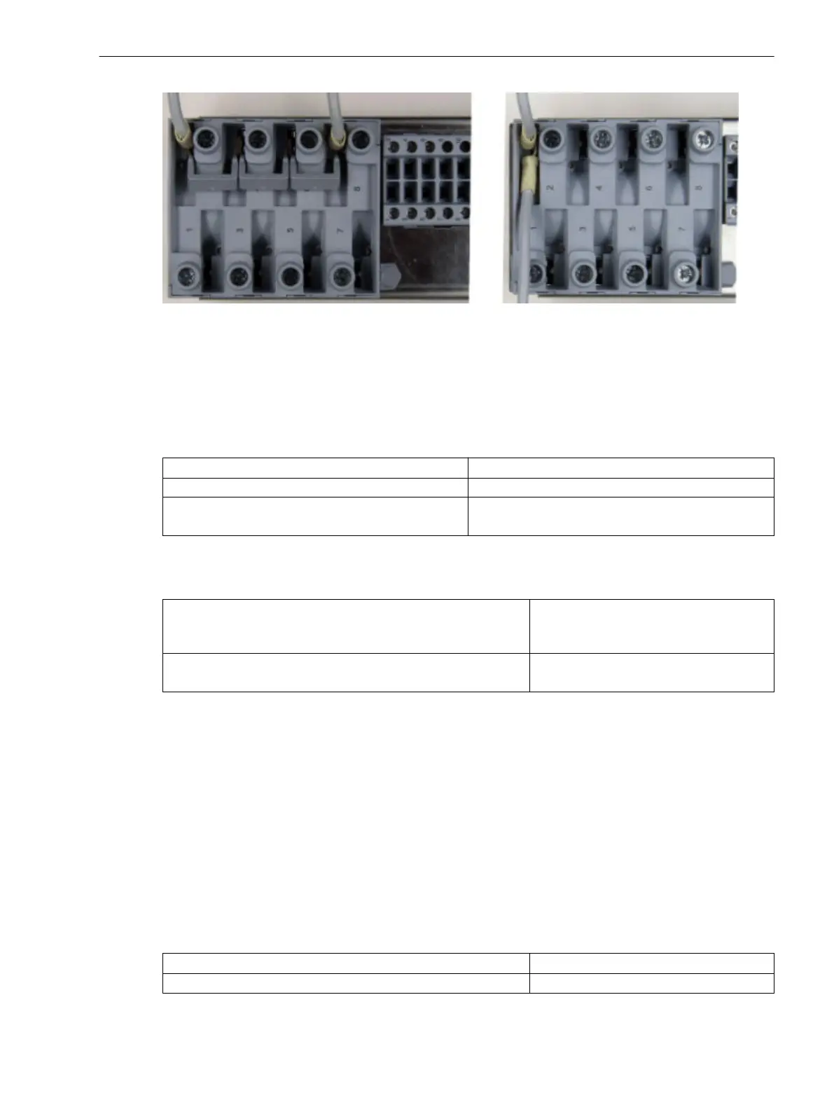
Figure 3-6 Current transformer connection
As single wires, solid conductors as well as stranded conductors with conductor sleeves can be used. Up to
two single wires with identical cross-sections can be used per connection.
Alternatively jumpers (Order No. C53207-A406-D193-1) can be used with terminal points in a stacked
arrangement. When using jumpers, only ring lugs are allowed.
When connecting single wires, the following cross-sections are allowed:
Cable cross-section:
AWG 14-10 (2.0 mm
2
to 5.2 mm
2
)
Connector sleeve with plastic collar L = 10 mm (0.39 in) or L = 12 mm (0.47 in)
Stripping length:
(when used without conductor sleeve)
15 mm (0.59 in)
Use exclusively solid copper conductors.
Mechanical Requirements
The fixing elements and the connected components are designed for the following mechanical requirements:
Permissible tightening torque at the terminal screw
2.7 Nm (23.9 lb.in)
With solid conducters the allowed
maximum tighting torque is 2 Nm
Permissible traction per connected conductor 80 N based on IEC 60947-1
(VDE 660, Part 100)
Connections of the Voltage Terminals
Fixing Elements
The fixing elements for the voltage transformer connection are part of the voltage terminal (housing side).
They have a stress-crack- and corrosion-resistant alloy. The head shape of the terminal screw allows for using a
flat screwdriver (4.0 mm x 0.8 mm / 0.16 in x 0.031 in) or a crosstip screwdriver (PZ1). PZ1 is recommended.
Cable Lugs and Wire Cross-sections
The connection mode available is the connection as single cable. As single cables, solid conductors as well as
stranded conductors with or without conductor sleeves can be used. We recommend using twin cable end
sleeves when connecting two single cables. We recommend the twin cable end sleeves of the series PN 966
144 from Tyco Electronics.
When connecting single cables, the following cross-sections are allowed:
Cable cross-sections:
AWG 20-14 (0.5 mm
2
to 2.0 mm
2
)
Connector sleeve with plastic collar L = 12 mm (0.47 in)
3.1.2.3
Mounting and Commissioning
3.1 Mounting and Connections
SIPROTEC 4, 7SJ80, Manual 319
E50417-G1140-C343-A8, Edition 12.2017
 Loading...


