[7sj6x-hochstromst-ie-20061212, 1, en_US]
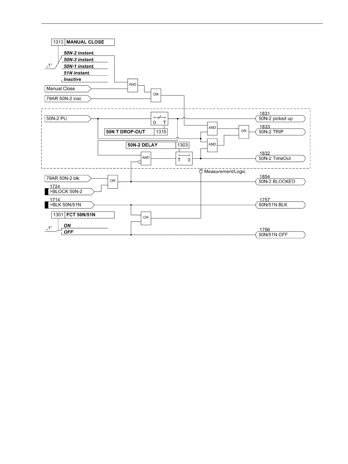
Figure 2-5
Logic diagram for 50N-2 high-set element
If parameter MANUAL CLOSE is set to 50N-2 instant. or 50N-3 instant. and manual close detection is
used, a pickup causes instantaneous tripping, even if the element is blocked via binary input. The same applies
to AR 50N-2 inst.
The same applies to 79 AR 50N-2 inst. or 79 AR 50N-3 inst.
Definite Time Overcurrent Elements 50-1, 50N-1
For each element an individual pickup value 50-1 PICKUP or 50N-1 PICKUP is set. Apart from Funda-
mental, the True RMS can also be measured. Each phase and ground current is compared separately with
the setting value 50-1 or 50N-1 for each element. If the respective value is exceeded, this is signaled. If the
inrush restraint feature (see below) is applied, either the normal pickup signals or the corresponding inrush
signals are output as long as inrush current is detected. After user-configured time delays 50-1 DELAY or
50N-1 DELAY have elapsed, a trip signal is issued if no inrush current is detected or inrush restraint is disa-
bled. If the inrush restraint feature is enabled and an inrush condition exists, no tripping takes place but a
message is recorded and displayed indicating when the overcurrent element time delay elapses. Trip signals
and signals on the expiration of time delay are available separately for each element. The dropout value is
approximately 95% of the pickup value for currents > 0.3 INom.
Pickup can be stabilized by setting dropout times 1215 50 T DROP-OUT or1315 50N T DROP-OUT. This
time is started and maintains the pickup condition if the current falls below the threshold. Therefore, the func-
tion does not drop out at high speed. The trip-command delay time 50-1 DELAY or 50N-1 DELAY continues
running in the meantime. After the dropout delay time has elapsed, the pickup is reported OFF and the trip
delay time is reset unless the threshold 50-1 or 50N-1 has been exceeded again. If the threshold is exceeded
again during the dropout delay time, the time is canceled. However, the trip-command delay time 50-1
2.2.3
Functions
2.2 Overcurrent Protection 50, 51, 50N, 51N
SIPROTEC 4, 7SJ80, Manual 59
E50417-G1140-C343-A8, Edition 12.2017
 Loading...


