[7sj6x_rueckfallverzoegerung_i_gr_erde_260803_he, 1, en_US]
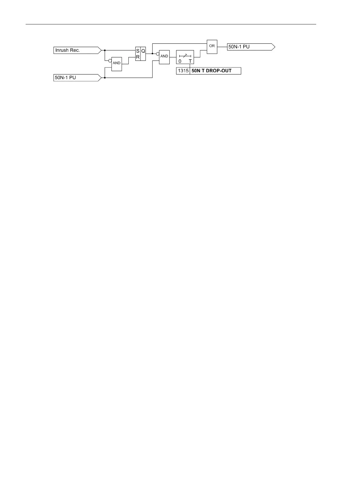
Figure 2-9 Logic of the dropout delay for 50N-1
Inverse Time Overcurrent Elements 51, 51N
Inverse time overcurrent elements are dependent on the ordering version. They always operate with an
inverse time Curve in accordance with IEC or ANSI standards. The characteristics and associated formulas are
given in the Technical Data.
When configuring one of the inverse-time characteristics, the definite-time elements 50-3, 50-2,and 50-1 are
also active (see Section "Definite-time High-set Current Elements 50-3, 50-2, 50N-3, 50N-2 " and "Definite-
time Overcurrent Elements 50-1, 50N-1 ").
A voltage restraint can optionally be set (see Section “Inverse Time Overcurrent Protection (Voltage-
controlled / Voltage-restraint”).
Pickup Behavior
For each element, an individual pickup value 51 PICKUP or 51N PICKUP is set. Apart from Fundamental,
the True RMS can also be measured. Each phase and ground current is separately compared with the setting
value 51 or 51N per element. If a current exceeds 1.1 times the setting value, the corresponding element picks
up and is signaled individually. If the inrush restraint function is used, either the normal pickup signals or the
corresponding inrush signals are issued as long as inrush current is detected. If the 51 element picks up, the
tripping time is calculated from the actual fault current flowing, using an integrating method of measurement.
The calculated tripping time depends on the selected tripping curve. Once this time has elapsed, a trip signal is
issued provided that no inrush current is detected or inrush restraint is disabled. If the inrush restraint function
is enabled and an inrush condition exists, no tripping takes place but a message is issued indicating when the
overcurrent element time delay elapses.
These elements can be blocked by the automatic reclosing feature (79 AR).
For ground current element 51N, the characteristic may be selected independently of the characteristic used
for phase currents.
Pickup values of elements 51 (phase currents) and 51N (ground current) and the relevant time multiplicators
may be set individually.
The following two figures show the logic diagrams for the inverse time overcurrent protection.
2.2.4
Functions
2.2 Overcurrent Protection 50, 51, 50N, 51N
62 SIPROTEC 4, 7SJ80, Manual
E50417-G1140-C343-A8, Edition 12.2017
 Loading...


