[sj6x-ueb-einph-kesselschut-020926-rei, 1, en_US]
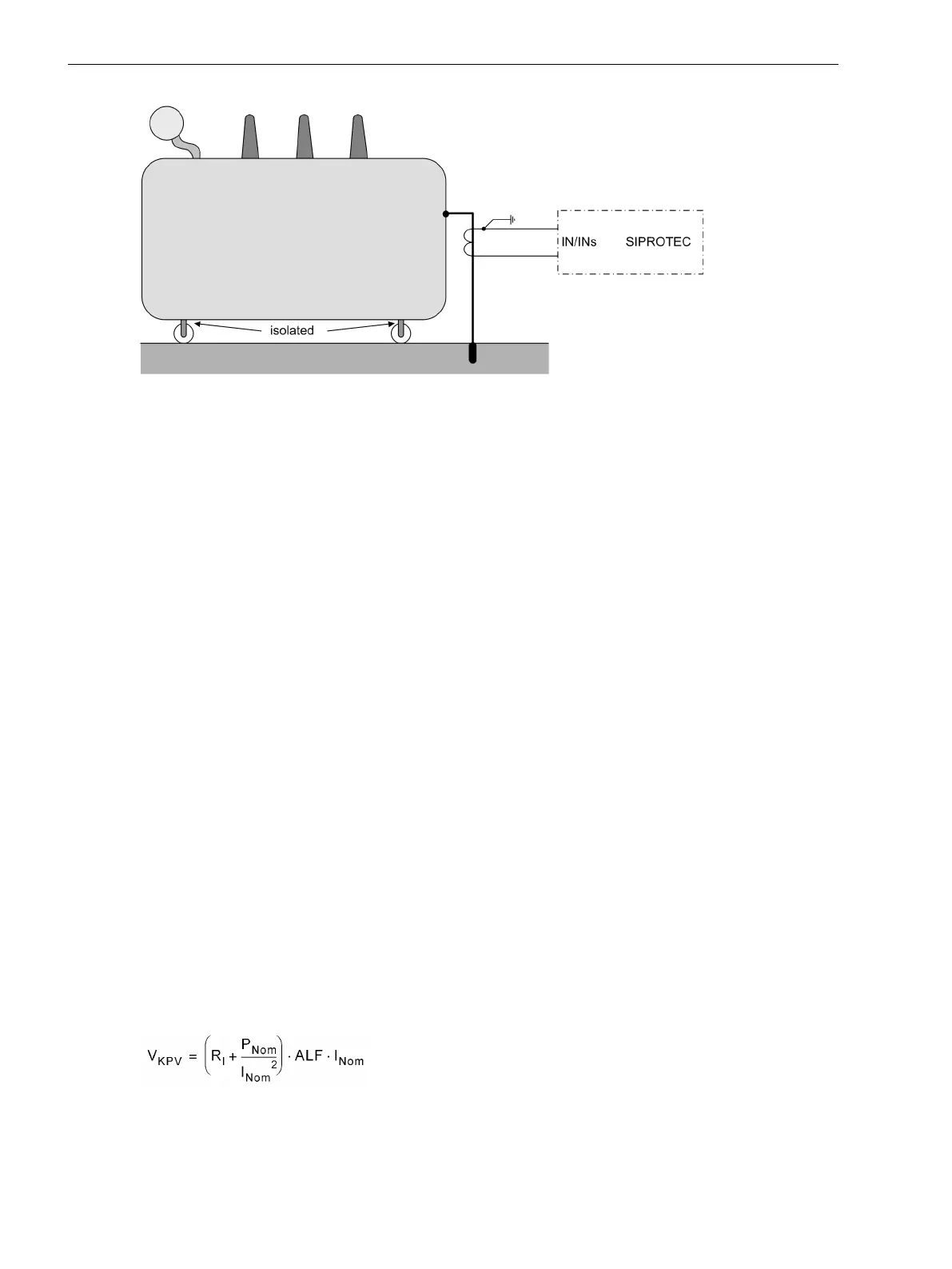
Figure 2-41 Principle of tank-leakage protection
Setting Notes
General
Single-phase time overcurrent protection can be set ON or OFF at address 2701 50 1Ph.
The settings are based on the particular application.
The pickup value for 50 1Ph-2 PICKUP is set in address2703, the pickup value for 50 1Ph-1 PICKUP at
address 2706. If only one element is required, set the one not required to ∞.
A trip time delay can be set in address 2704 50 1Ph-2 DELAY for the 50-2 element and for the 50-1 element
in address 2707 50 1Ph-1 DELAY. With setting 0 s no delay takes place.
The selected times are additional time delays and do not include the operating time (measuring time, etc.) of
the elements. The delay can also be set to ∞; the corresponding element will then not trip after pickup, but
the pickup is reported.
Special notes are given in the following for the use as high-impedance unit protection and tank leakage
protection.
Application as High-impedance Protection
The application as high-impedance protection requires that neutral point current detection is possible in the
system in addition to phase current detection (see example in Figure 2-40). Furthermore, a sensitive input
transformer must be available at device input Ι
NS
. In this case, only the pickup value for single-phase overcur-
rent protection is set at the 7SJ80 device for the current at input Ι
NS
.
The entire function of high-impedance protection is, however, dependent on the interaction of current trans-
former characteristics, external resistor R and voltage across R. The following section gives information on this
topic.
Current Transformer Data for High-impedance Protection
All current transformers must have an identical transformation ratio and nearly equal knee-point voltage. This
is usually the case if they are of equal design and identical rated data. The knee-point voltage can be approxi-
mately calculated from the rated data of a CT as follows:
[ueb-einph-saetigungsspannung-021026-rei, 1, en_US]
V
KVP
Knee-point voltage
2.5.4
Functions
2.5 Single-Phase Overcurrent Protection
116 SIPROTEC 4, 7SJ80, Manual
E50417-G1140-C343-A8, Edition 12.2017

 Loading...


