R
i
Internal burden of the CT
P
Nom
Nominal power of the CT
I
Nom
Secondary nominal current of CT
ALF Rated accuracy limit factor of the CT
The nominal current, nominal power and accuracy limit factor are normally stated on the rating plate of the
current transformer, e.g.
Current transformer 800/5; 5P10; 30 VA
That means
Ι
Nom
= 5 A (from 800/5)
ALF = 10 (from 5P10)
P
Nom
= 30 VA
The internal burden is often stated in the test report of the current transformer. If not, it can be derived from a
DC measurement on the secondary winding.
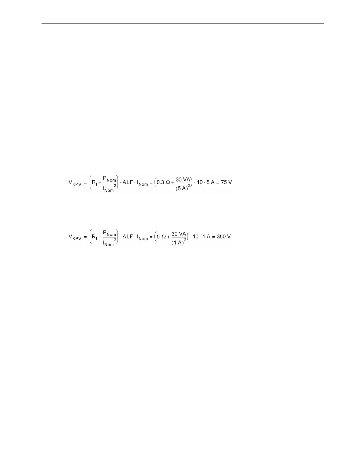
Calculation Example:
CT 800/5; 5P10; 30 VA with R
i
= 0.3 Ω
[ueb-einph-saettigungssp-beisp1-021026-rei, 1, en_US]
or
CT 800/1; 5P10; 30 VA with R
i
= 5 Ω
[ueb-einph-saettigungssp-beisp2-021026-rei, 1, en_US]
Besides the CT data, the resistance of the longest connection lead between the CTs and the 7SJ80 device must
be known.
Stability with High-impedance Protection
The stability condition is based on the following simplified assumption: If there is an external fault, one of the
current transformers gets totally saturated. The other ones will continue transmitting their (partial) currents.
In theory, this is the most unfavorable case. Since, in practice, it is also the saturated transformer which
supplies current, an automatic safety margin is guaranteed.
Figure 2-42 shows a simplified equivalent circuit. CT1 and CT2 are assumed as ideal transformers with their
inner resistances R
i1
and R
i2
. R
a
are the resistances of the connecting cables between current transformers and
resistor R. They are multiplied by 2 as they have a forward and a return line. R
a2
is the resistance of the longest
connecting cable.
CT1 transmits current Ι
1
. CT2 shall be saturated. Because of saturation the transformer represents a low-resis-
tance shunt which is illustrated by a dashed short-circuit line.
R >> (2R
a2
+ R
i2
) is a further prerequisite..
Functions
2.5 Single-Phase Overcurrent Protection
SIPROTEC 4, 7SJ80, Manual 117
E50417-G1140-C343-A8, Edition 12.2017

 Loading...


