[ueb-einph-anordnung-020926-rei, 1, en_US]
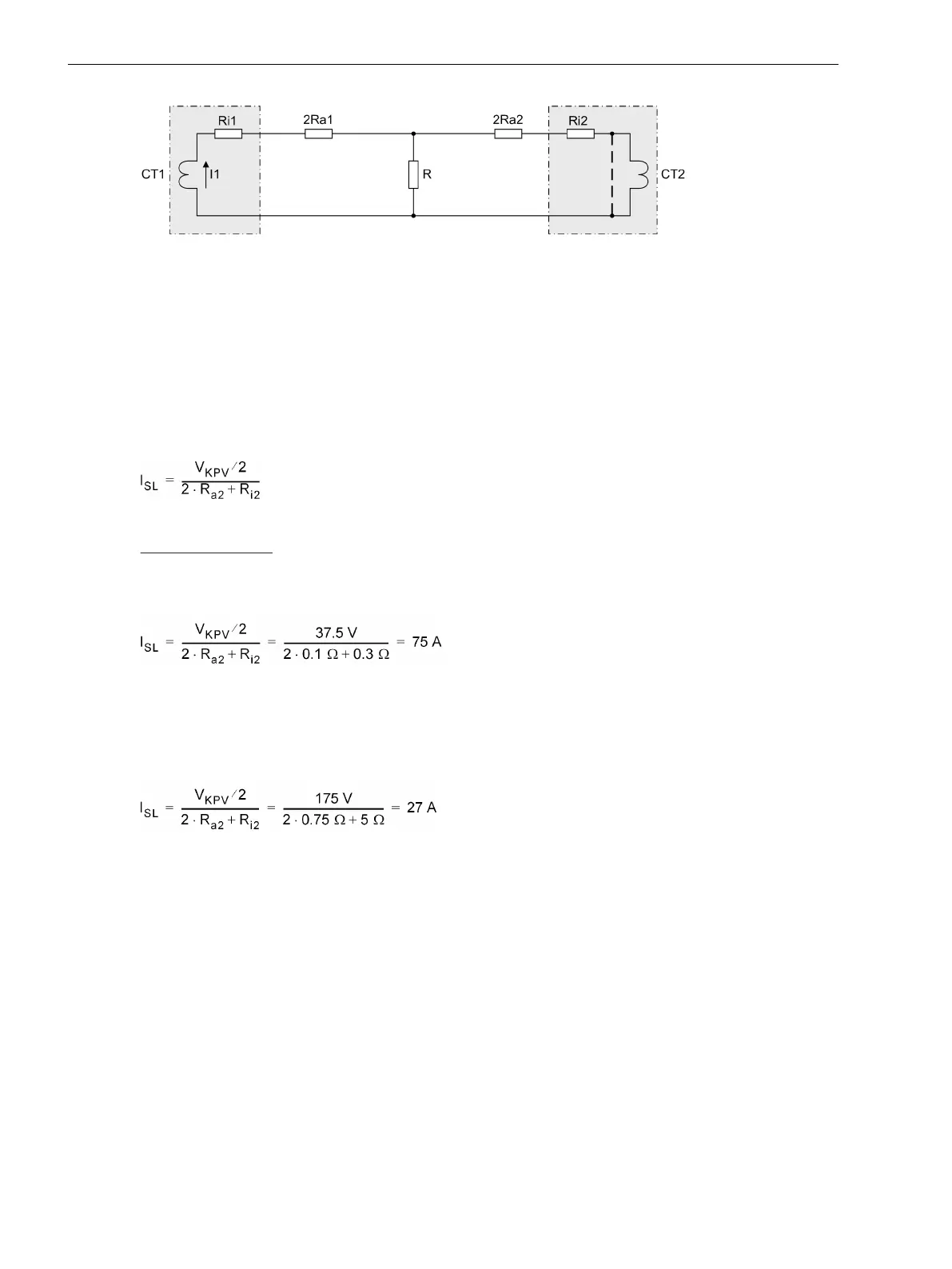
Figure 2-42 Simplified equivalent circuit of a circulating current system for high-impedance protection
The voltage across R is then
V
R
= Ι
1
· ( 2R
a2
+ R
i2
)
It is assumed that the pickup value of the 7SJ80 corresponds to half the knee-point voltage of the current
transformers. In the balanced case results
V
R
= V
S
/ 2
This results in a stability limit Ι
SL
, i.e. the maximum through-fault current below which the scheme remains
stable:
[ueb-einph-stabilitaetslimit-021026-rei, 1, en_US]
Calculation Example:
For the 5 A CT as above with V
S
= 75 V and R
i
= 0.3 Ω
longest CT connection lead 22 m (24.06 yd) with 4 mm
2
cross-section, this corresponds to R
a
= 0.1 Ω
[ueb-einph-stabilitaetslimit-5a-021026-rei, 1, en_US]
that is 15 × rated current or 12 kA primary.
For the 1 A CT as above with V
S
= 350 V and R
i
= 5 Ω
longest CT connection lead 107 m (117.02 yd) with 2.5 mm
2
cross-section, this corresponds R
a
= 0.75 Ω
[ueb-einph-stabilitaetslimit-1a-021026-rei, 1, en_US]
that is 27 × rated current or 21.6 kA primary.
Sensitivity with High-impedance Protection
The voltage present at the CT set is forwarded to the protective relay across a series resistor R as proportional
current for evaluation. The following considerations are relevant for dimensioning the resistor:
As already mentioned, it is desired that the high-impedance protection should pick up at half the knee-point
voltage of the CT's. The resistor R can calculated on this basis.
Since the device measures the current flowing through the resistor, resistor and measuring input of the device
must be connected in series. Since, furthermore, the resistance shall be high-resistance (condition: R >> 2R
a2
+
R
i2
, as mentioned above), the inherent resistance of the measuring input can be neglected. The resistance is
then calculated from the pickup current Ι
pu
and half the knee-point voltage:
Functions
2.5 Single-Phase Overcurrent Protection
118 SIPROTEC 4, 7SJ80, Manual
E50417-G1140-C343-A8, Edition 12.2017

 Loading...


