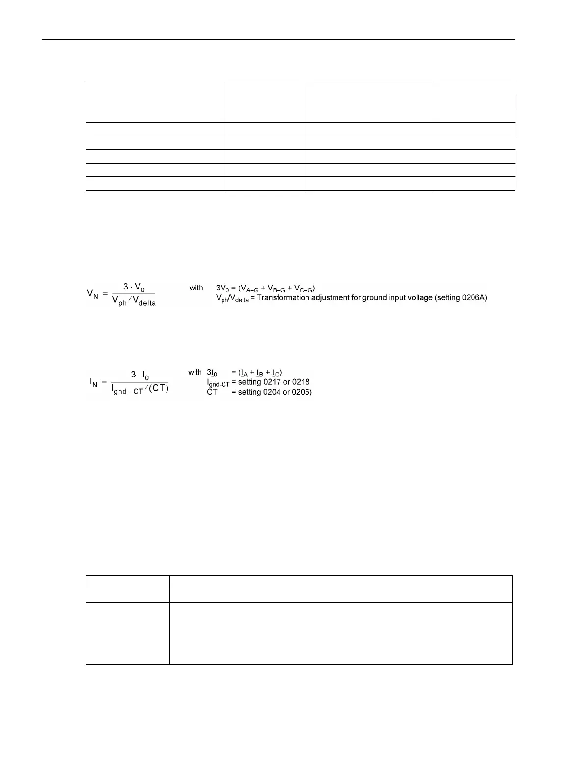
Table 2-22 Legend for the conversion formulae
Parameter Address Parameter Address
CT PRIMARY
204
Ignd-CT PRIM
217
CT SECONDARY
205
Ignd-CT SEC
218
Vnom PRIMARY
202
Vph / Vdelta
206
Vnom SECONDARY
203
FullScaleVolt.
1101
FullScaleCurr.
1102
VXnom PRIMARY
232
Ignd2-CT PRIM.
238
VXnom SECONDARY
233
Ignd2-CT SEC.
239
Depending on the type of device ordered and the device connections, some of the operational measured
values listed below may not be available.
The phase–to–ground voltages are either measured directly, if the voltage inputs are connected phase–to–
ground, or they are calculated from the phase–to–phase voltages V
A–B
and V
B–C
and the displacement voltage
V
N
.
The displacement voltage V
N
is either measured directly or calculated from the phase-to-ground voltages:
[verlagerungsspannunguen-020315-wlk, 1, en_US]
Please note that value V
0
is indicated in the operational measured values.
The ground current Ι
N
is either measured directly or calculated from the conductor currents.
[erdstrom-020315-wlk, 1, en_US]
Upon delivery, the power and operating values are set in such manner that power in line direction is positive.
Active components in line direction and inductive reactive components in line direction are also positive. The
same applies to the power factor cosϕ. It is occasionally desired to define the power drawn from the line (e.g.
as seen from the consumer) positively. Using parameter 1108 P,Q sign the signs for these components can
be inverted.
The calculation of the operational measured values is also performed during a fault. The values are updated in
intervals of > 0.3 s and < 1 s.
Transfer of Measured Values
Measured values can be transferred via the interfaces to a central control and storage unit.
The measuring range in which these values are transmitted depend on the protocol and, if necessary, addi-
tional settings.
Protocol
Transmittable measuring range, format
IEC 60870-5-103 0 to 240 % of the measured value.
IEC 61850 The primary operational measured values are transmitted.
The measured values as well as their unit format are set out in detail in manual PIXIT
7SJ.
The measured values are transmitted in “Float” format. The transmitted measuring
range is not limited and corresponds to the operational measurement.
2.23.3.2
Functions
2.23 Auxiliary Functions
290 SIPROTEC 4, 7SJ80, Manual
E50417-G1140-C343-A8, Edition 12.2017
 Loading...


