Inverse Time Overcurrent Protection 51V (Voltage-controlled /
Voltagerestraint)
Undervoltage Consideration
The inverse time overcurrent protection is provided with an undervoltage detection that can be disabled
(address 1223 VOLT. INFLUENCE). This function can influence overcurrent detection by means of two
different methods:
•
Voltage-controlled: If a set voltage threshold is undershot, the overcurrent element is released.
•
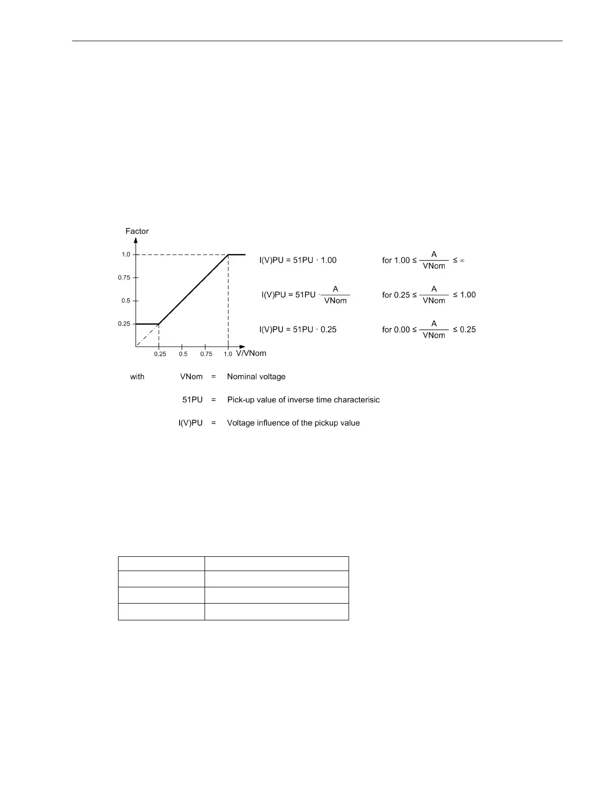
Voltage-restraint: The pickup threshold of the overcurrent element depends on the voltage magnitude.
A lower voltage decreases the current pickup value (see Figure 2-13). In the range between V/V
Nom
= 1.00
to 0.25 a linear, directly proportional dependence is realized, and therefore the following applies:
[spannungsabhaengigkeit-des-anregewertes, 1, en_US]
Figure 2-12 Voltage influence of the pickup value
The 51 PICKUP value is decreased proportional to the voltage decrease. Consequently, for constant current Ι
the Ι/ 51 PICKUP ratio is increased and the tripping time is reduced. Compared with the standard curves repre-
sented in Section “Technical Data” the tripping curve shifts to the left side as the voltage decreases.
Switching to the lower pickup value or decreasing the pickup threshold is carried out phase-selectively. The
assignment of voltages to current-carrying phases is shown in the following table.
Table 2-3
Controlling voltages in relation to the fault currents
Strom Spannung
Ι
A
V
A
– V
B
Ι
B
V
B
– V
C
Ι
C
V
C
– V
A
In order to avoid an unwanted operation in case of a voltage transformer fault, a function blocking is imple-
mented via a binary input controlled by the voltage transformer protection breaker as well as via the device-
internal measuring voltage failure detection ("Fuse Failure Monitor").
The following two figures show the logic diagrams for the inverse time overcurrent protection with under-
voltage consideration.
2.2.5
Functions
2.2 Overcurrent Protection 50, 51, 50N, 51N
SIPROTEC 4, 7SJ80, Manual 65
E50417-G1140-C343-A8, Edition 12.2017

 Loading...


