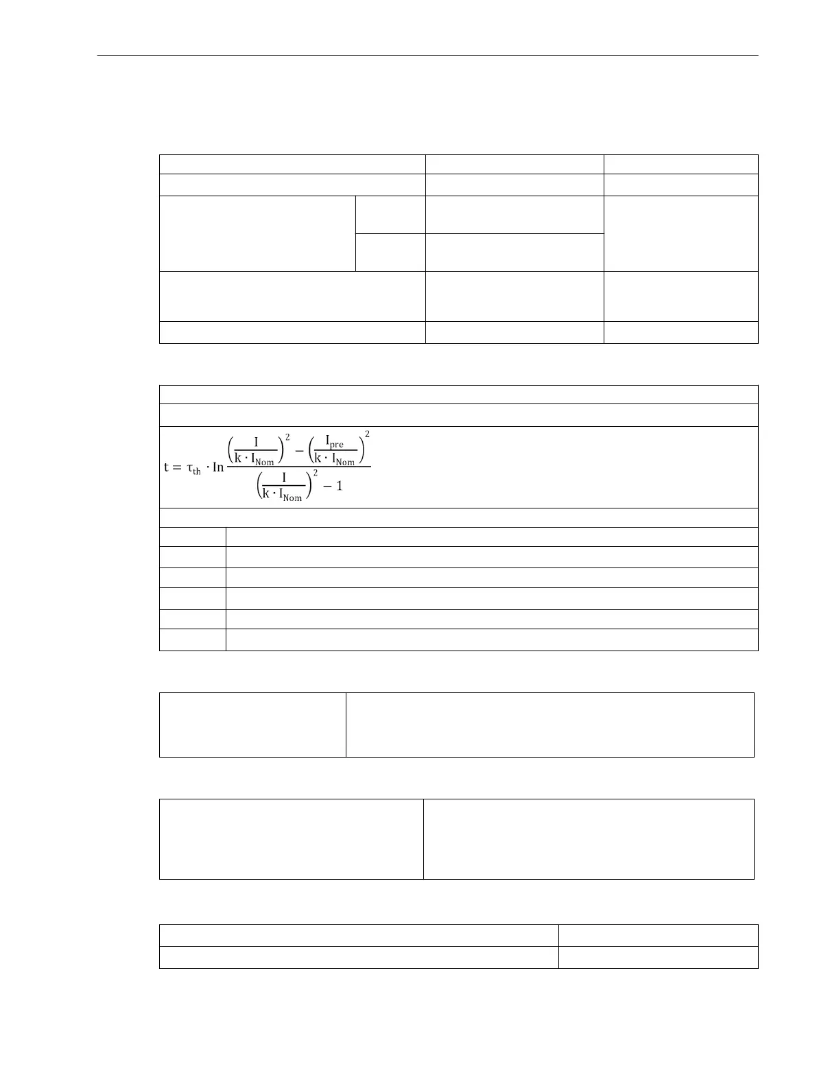
Thermal Overload Protection
Setting ranges / increments
Factor k according to IEC 60255-8 0.10 to 4.00 Increments 0.01
Time constant τ
th
1.0 min to 999.9 min Increments 0.1 min
Current alarm element Ι
Alarm
for Ι
Nom
=
1 A
0.10 A to 4.00 A Increments 0.01 A
for Ι
Nom
=
5 A
0.50 A to 20.00 A
Extension with machine at rest kτ factor 1.0 to 10.0 relative to the time
constant for the machine
running
Increments 0.1
Dropout time (emergency start) T
Emergency
10 s to 15000 s Increments 1 s
Trip Characteristic
Formula for primary values:
Trip Characteristic curve for Ι / (k ⋅ Ι
Nom
) ≤8
with
t Trip time in minutes
τ
th
Heating-up time constant
Ιn
Actual load current
Ι
pre
Preload current
k Setting factor per IEC 60255-8
Ι
Nom
Nominal current for the protected object
Dropout Ratios
Θ/Θ
Trip
Θ/Θ
Alarm
Ι/Ι
Alarm
Drops out with Θ
Alarm
approx. 0.99
approx. 0.97
Tolerances
Referring to k ·
Ι
Nom
Referring to Trip Time
2 % or 10 mA for Ι
Nom
= 1 A, or 50 mA für Ι
Nom
= 5 A,
2 % class according to IEC 60255-8
3 % or 1 s for Ι/(k ·Ι
Nom
) > 1,25;
3 % class according to IEC 60255-8
Influencing Variables Referring to k · Ι
Nom
Auxiliary DC voltage in range 0.8 ≤ V
Aux
/V
AuxNom
≤ 1,15 1 %
Temperature in range –5 °C (23 °F) ≤ Θ
amb
≤ 55 °C (131 °F) 0.5 %/10 K
4.13
Technical Data
4.13 Thermal Overload Protection
SIPROTEC 4, 7SJ80, Manual 393
E50417-G1140-C343-A8, Edition 12.2017

 Loading...


