EasyManuals Logo

Siemens SIPROTEC 7SJ80 User Manual

Siemens SIPROTEC 7SJ80
562 pages
To Next Page IconTo Next Page
To Previous Page IconTo Previous Page
Page #89 background imageLoading...
Page #89 background image
[7sj6x_gerueberstromzeit_abh_ueberstrom_ip-150502-kn, 1, en_US]
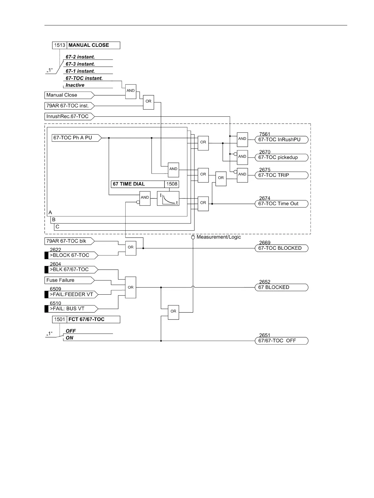
Figure 2-24
Logic diagram for the directional overcurrent protection: 67-TOC relay element
Interaction with Fuse Failure Monitor (FFM)
False or undesired tripping can be caused by a measuring voltage that can be caused by either short-circuit or
broken wire in the voltage transformer's secondary system or an operation of the voltage transformer fuse.
Failure of the measuring voltage in one or two phases can be detected, and the directional time overcurrent
elements (Dir Phase and Dir Ground) can be blocked, see logic diagrams.
Undervoltage protection, sensitive ground fault detection and synchronization are also blocked in this case.
For additional information on the operation of the fuse failure monitor, see Section 2.11.1 Measurement
Supervision.
2.3.5
Functions
2.3 Directional Overcurrent Protection 67, 67N
SIPROTEC 4, 7SJ80, Manual 89
E50417-G1140-C343-A8, Edition 12.2017

Table of Contents

Other manuals for Siemens SIPROTEC 7SJ80

Questions and Answers:

Question and Answer IconNeed help?

Do you have a question about the Siemens SIPROTEC 7SJ80 and is the answer not in the manual?

Siemens SIPROTEC 7SJ80 Specifications

General IconGeneral
Rated Frequency50/60 Hz
Rated Current1 A / 5 A
Operating Temperature-25°C to +55°C
Storage Temperature-40°C to +70°C
Current Transformer Inputs4
ApplicationProtection of feeders, motors, transformers, and generators
Rated Voltage100-240 V AC/DC
Communication ProtocolsIEC 61850, Modbus, DNP3, IEC 60870-5-103
DisplayGraphical LCD
MountingFlush mounting
Protection FunctionsOvercurrent, Earth fault
Communication InterfacesEthernet, RS485
HousingPlastic
WeightApprox. 1.5 kg

Related product manuals