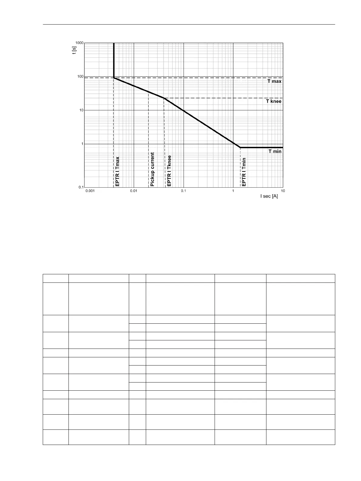
[7SJ80_knickpkt-kennlinie, 1, en_US]
Figure 2-85
Tripping Time Characteristic Curves of the Inverse-Time Ground-Fault Protection with Loga-
rithmic-Inverse Knee-Point Characteristic Curve, Example EPTR
Settings
Addresses which have an appended “A” can only be changed with DIGSI, under “Additional Settings”.
The table indicates region-specific default settings. Column C (configuration) indicates the corresponding
secondary nominal current of the current transformer.
Addr.
Parameter C Setting Options Default Setting Comments
3101 Sens. Gnd Fault OFF
ON
ON with GF log
Alarm Only
OFF (Sensitive) Ground Fault
3102 CT Err. I1 1A 0.001 .. 1.600 A 0.050 A Current I1 for CT Angle
Error
5A 0.005 .. 8.000 A 0.250 A
3102 CT Err. I1 1A 0.05 .. 35.00 A 1.00 A Current I1 for CT Angle
Error
5A 0.25 .. 175.00 A 5.00 A
3103 CT Err. F1 0.0 .. 5.0 ° 0.0 ° CT Angle Error at I1
3104 CT Err. I2 1A 0.001 .. 1.600 A 1.000 A Current I2 for CT Angle
Error
5A 0.005 .. 8.000 A 5.000 A
3104 CT Err. I2 1A 0.05 .. 35.00 A 10.00 A Current I2 for CT Angle
Error
5A 0.25 .. 175.00 A 50.00 A
3105 CT Err. F2 0.0 .. 5.0 ° 0.0 ° CT Angle Error at I2
3106 VPH MIN 10 .. 100 V 40 V L-Gnd Voltage of Faulted
Phase Vph Min
3107 VPH MAX 10 .. 100 V 75 V L-Gnd Voltage of Unfaulted
Phase Vph Max
3109 64-1 VGND 1.8 .. 200.0 V; ∞ 40.0 V 64-1 Ground Displacement
Voltage
2.12.6
Functions
2.12 Ground Fault Protection 64, 67N(s), 50N(s), 51N(s)
SIPROTEC 4, 7SJ80, Manual 193
E50417-G1140-C343-A8, Edition 12.2017
 Loading...


