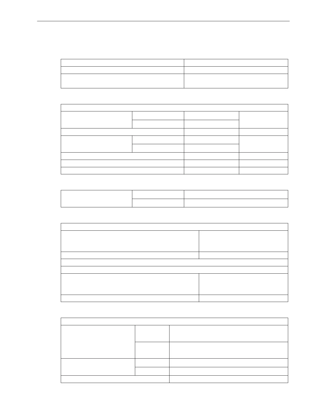
Undervoltage-controlled reactive power protection (27/Q)
Measured Values / Modes of Operation
3-phase
Ι1, V, Q,
Measuring method for Ι, V
Fundamental wave
Pickup when Exceeding threshold value or
falling below threshold value
Setting Ranges / Increments
Pickup thresholds:
Current Ι
1
for Ι
Nom
= 1 A
0.02 to 0.20 A Increments 0.01 A
for Ι
Nom
= 5 A
0.10 to 1.00 A
Voltage V 10.0 to 210.00 V Increments 0.1 V
Power Q
for Ι
Nom
= 1 A
1.0 to 100 VAR Increments 0.01 VAR
for Ι
Nom
= 5 A
5.0 to 500 VAR
Tripping delay time 0.00 to 60.00 s Increments 0.01 s
Release delay time 0.00 to 3600.00 s Increments 0.01 s
Dropout delay 0.00 to 60.00 s Increments 0.01 s
Function Limits
Power measurement 3-phase
for Ι
Nom
= 1 A
Positive sequence system current > 0.03 A
for Ι
Nom
= 5 A
Positive sequence system current > 0.15 A
Times
Pickup times:
QU protection
typical
maximum (small signals and thresholds)
approx. 120 ms
approx. 350 ms
Binary input approx. 20 ms
Dropout times:
QU protection
typical
maximum
< 50 ms
< 350 ms
Binary input < 10 ms
Tolerances
Pickup thresholds:
Current
for Ι
Nom
= 1 A 1% of set value or 10 mA at Ι
Nom
≥ 0.03 A
2% of set value or 20 mA bei Ι
Nom
< 0.03 A
for Ι
Nom
= 5 A 1% of set value or 50 mA at Ι
Nom
≥ 0.25 A
2% of set value or 100 mA at Ι
Nom
<0.25 A
Current (symmetrical compo-
nents)
for Ι
Nom
= 1 A
2% of set value or 20 mA
for Ι
Nom
= 5 A
2% of set value or 100 mA
Voltage 1% of set value or 0.1 V
4.12
Technical Data
4.12 Undervoltage-controlled reactive power protection (27/Q)
SIPROTEC 4, 7SJ80, Manual 391
E50417-G1140-C343-A8, Edition 12.2017

 Loading...


