[7sj80-eptr-tss, 2, en_US]
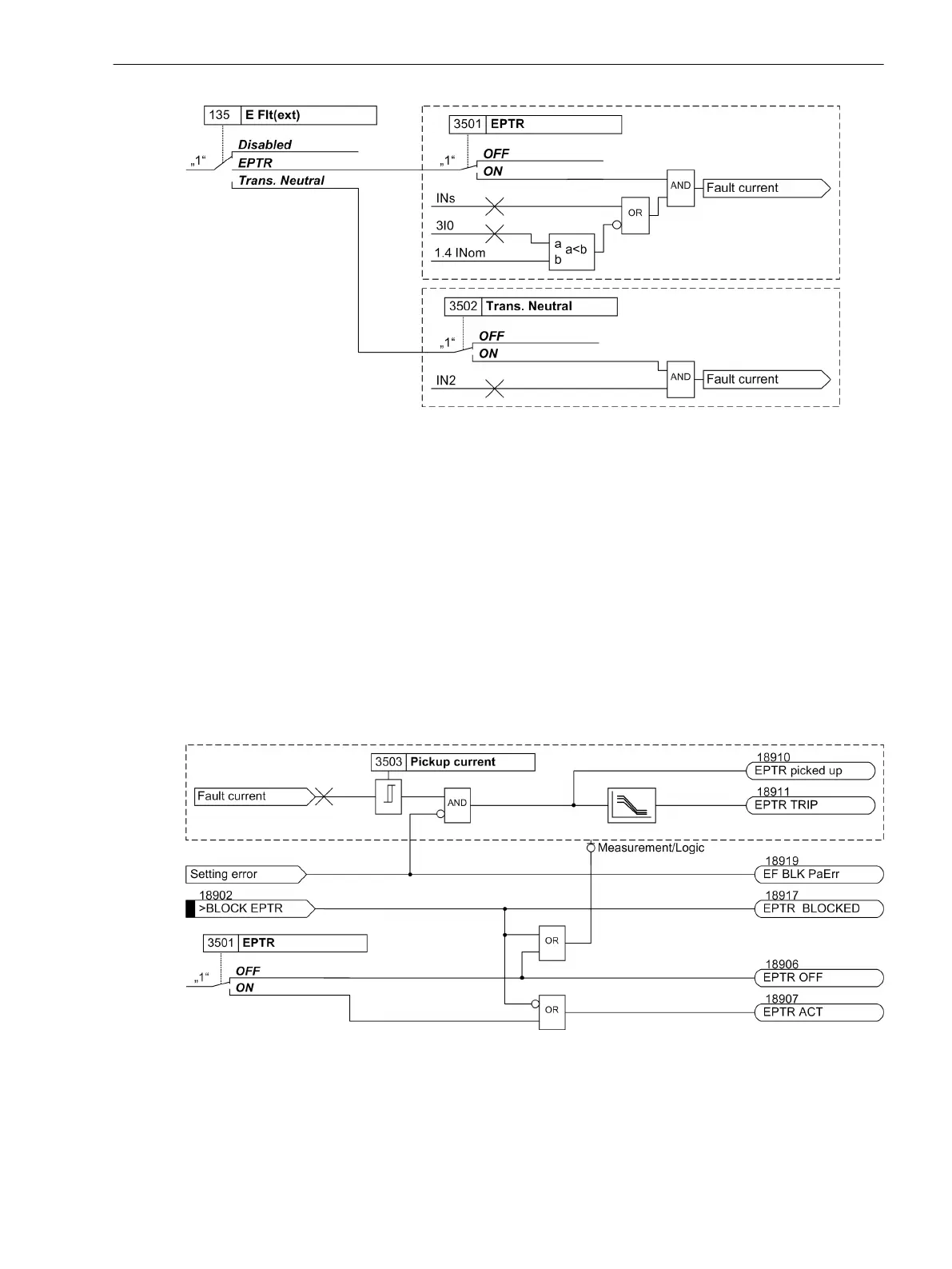
Figure 2-78 Activation of the Functions EPTR or Transformer Neutral Point (TNP)
Ground-Fault Protection EPTR - B
For low fault currents (< 0.95 * 1.4 Ιn),the function works with the ground current measured on the 4th
current input. For higher fault currents (≥ 1.4 Ιn), ), the current 3I0 built from the phase currents is used. You
can find a connection example in the Appendix (C.1 Connection Examples for Current and Voltage Trans-
formers).
If you use the function EPTR, you must set the connection type (CT Connect., address 251 ) to A, B, C,
(Gnd).
If you use the function EPTR, you must set the connection type (). The pickup current of the function and the
course of the characteristic curve can be set. You can find information on the setting values in Section
2.12.5 Setting Notes.
Logic
The following figure shows the logic diagram of the function EPTR.
[7sj80-lo-eptr, 2, en_US]
Figure 2-79 Logic of the Ground-Fault Detection EPTR
2.12.3.2
Functions
2.12 Ground Fault Protection 64, 67N(s), 50N(s), 51N(s)
SIPROTEC 4, 7SJ80, Manual 183
E50417-G1140-C343-A8, Edition 12.2017
 Loading...


