EasyManuals Logo

Siemens SIPROTEC 7SJ80 User Manual

Siemens SIPROTEC 7SJ80
562 pages
To Next Page IconTo Next Page
To Previous Page IconTo Previous Page
Page #144 background imageLoading...
Page #144 background image
[lo-recl-rel-qvp-20120319, 2, en_US]
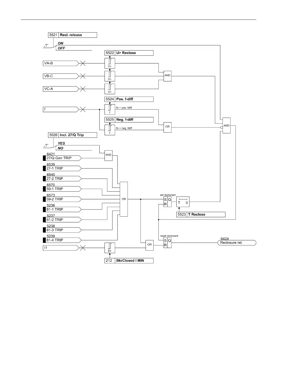
Figure 2-53
Logic diagram of QU protection restarting
Setting Notes
General
Configuration of the protection functions at address 155 27/Q-Protection defines whether the QU protec-
tion is Enabled or Disabled.
At address 5501 27/Q-Protection the QU protection function can be switched ON or OFF.
The release current is entered at address 5502 I-Release. The default setting is at 10 % of the rated current.
The threshold is one of the pickup criteria for tripping.
At address 5503 Inrush blk you can activate the blocking when inrush has been detected.
2.9.2
Functions
2.9 Undervoltage-controlled reactive power protection (27/Q)
144 SIPROTEC 4, 7SJ80, Manual
E50417-G1140-C343-A8, Edition 12.2017

Table of Contents

Other manuals for Siemens SIPROTEC 7SJ80

Questions and Answers:

Question and Answer IconNeed help?

Do you have a question about the Siemens SIPROTEC 7SJ80 and is the answer not in the manual?

Siemens SIPROTEC 7SJ80 Specifications

General IconGeneral
Rated Frequency50/60 Hz
Rated Current1 A / 5 A
Operating Temperature-25°C to +55°C
Storage Temperature-40°C to +70°C
Current Transformer Inputs4
ApplicationProtection of feeders, motors, transformers, and generators
Rated Voltage100-240 V AC/DC
Communication ProtocolsIEC 61850, Modbus, DNP3, IEC 60870-5-103
DisplayGraphical LCD
MountingFlush mounting
Protection FunctionsOvercurrent, Earth fault
Communication InterfacesEthernet, RS485
HousingPlastic
WeightApprox. 1.5 kg

Related product manuals